wc_tx004029gb_FM10.fm
128
Rammer
Disassembly and Reassembly
Continued from the previous page.
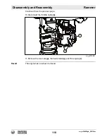
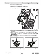
6. Reach through the slotted hole
(q)
in the crank gear and release the large
retaining ring
(m)
.
7. Thread two M8 socket head cap screws, or threaded rods, through the pusher
holes
(p)
in the crank gear. Turn the screws into the crank gear to free the crank
gear and the bearing from the cover.
8. Remove the small retaining ring
(j)
holding the bearing
(k)
to the crank gear.
9. Pull the bearing free of the shaft using the split puller
(s)
and a 2-jaw bearing
puller
(t)
.
10.Remove the small retaining ring
(u)
that holds the connecting rod and the
bearing
(n)
to the crank gear.
11.Pull the connecting rod
(d)
off the crank gear with a 2-jaw bearing puller.
12.Press the bearing
(n)
out of the connecting rod.
13.The needle bearing
(h)
remains intact in the crankcase cover. Inspect the
needle bearing for wear and, if damaged, remove it by using a slide hammer or
similar pulling device.
Result
The crankcase has now been removed.
wc_gr012874
e
b
h
j
k
p
q
m
t
s
m
c
d
n
u
a
Summary of Contents for BS 50-4s, BS 50-4As
Page 1: ...Repair Manual Vibratory Rammer 5100018465 01 1015 5 1 0 0 0 1 8 4 6 5 EN...
Page 6: ...wc_tx004061gb_FM10 fm 6 Rammer Foreword...
Page 10: ...Table of Contents Rammer wc_br5100018465_FM10TOC fm 10...
Page 180: ...wc_td000553gb_FM10 fm 180 Rammer Technical Data Notes...
Page 192: ......
Page 193: ......


