VibrationVIEW Help
205
© 1995-2005 Vibration Research Corporation. All rights reserved.
5
Control Centers
5.1
Overview
Control Centers
The control centers are docking toolbars that can be:
·
Attached to either the left or right side of the
VibrationVIEW
window
·
Detached and moved independently
·
Turned on/off by selecting the
menu command.
Test Control Centers
·
·
·
·
Classical Shock Control Center
·
Field Data Replicator Control Center
·
5.2
System Check
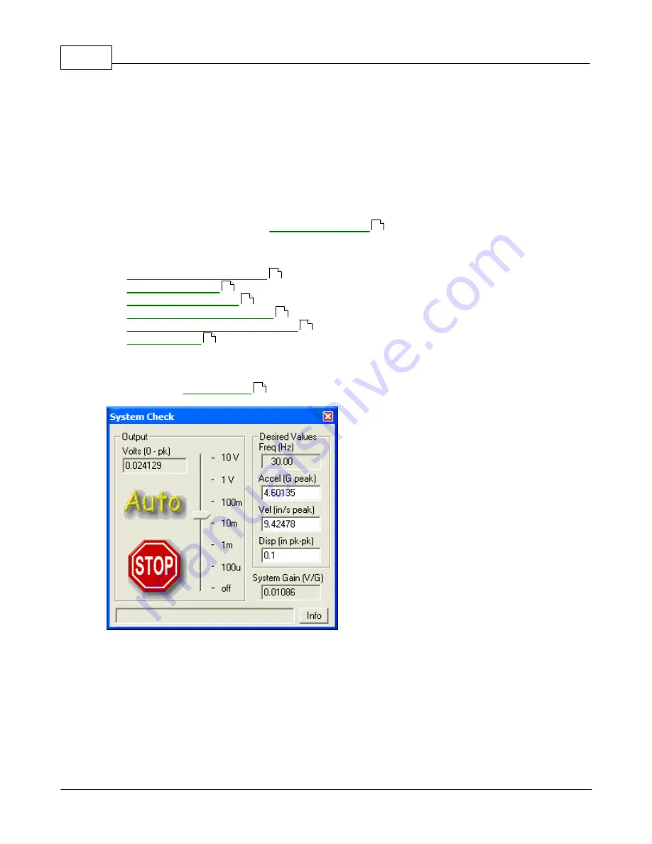
System Check
Use this dialog box to check the system operation. We recommend that you perform this function as a
prelude to any new testing operation. This is a good way to verify that the accelerometer, amplifier,
shaker and control system are all functioning. To use, place a displacement wedge on your shaker
table. The operation defaults are 0.10 inches at 30 Hz. Turn the shaker on. Click the "Auto" button.
Watch the shaker table carefully. It should begin to oscillate at a visible level of 0.10 inches.
Auto
: This button automatically adjusts the output voltage so that the channel 1 input matches the
Desired Values of Acceleration, Velocity, and Displacement.
Stop
: This button immediately returns the output voltage to 0 (i.e. turn the output off).
123
205
206
208
209
211
309
205
Summary of Contents for VibrationVIEW
Page 15: ...Document Revision Part I ...
Page 17: ...How To Part II ...
Page 96: ...Menu commands Part III ...
Page 142: ...Test Definition Part IV ...
Page 217: ...Control Centers Part V ...
Page 227: ...Accelerometer Toolbars Part VI ...
Page 231: ...Stop Codes Part VII ...
Page 263: ...Typical Views Part VIII ...
Page 268: ...VibrationVIEW Help 255 1995 2005 Vibration Research Corporation All rights reserved ...
Page 269: ...Dialog Boxes Part IX ...
Page 303: ...Windows Elements Part X ...
Page 309: ...APPENDIX Part XI ...
Page 311: ...APPENDIX 298 1995 2005 Vibration Research Corporation All rights reserved ...


