VibrationVIEW Help
9
© 1995-2005 Vibration Research Corporation. All rights reserved.
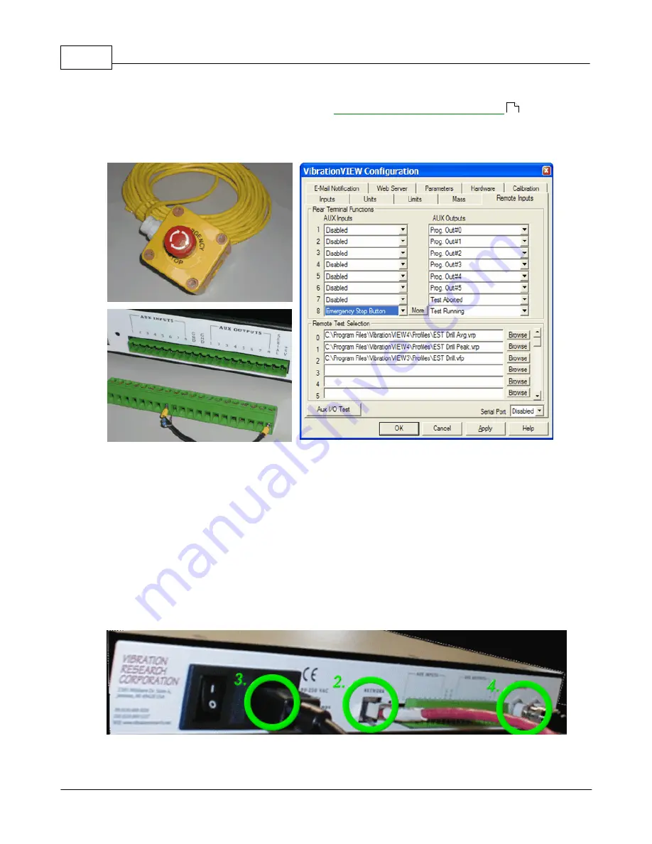
The E-Stop is wired into the green Phoenix connector at the rear of the 8500 i/o box. The software is
then set to recognize the E-Stop by going to the
Configuration menu...Remote Inputs
select the
proper Input pull-down to read "
Emergency Stop Button
" and then click "
Apply
". The controller will
now only allow a test to run if there is continuity at the defined E-Stop location on the Phoenix
connector.
Contact VIbration Research for additional information
2.2.5
How to install the hardware
How to install the hardware
Connecting the
VibrationVIEW
I/O hardware:
1.
Set up the computer in the conventional configuration, with power cables, mouse, keyboard, and
monitor.
2.
Connect the VR8500 network port to the dedicated network card in the computer using the
included yellow crossover cable.
If your VR8500 is labeled "Adapter Cable Required", the included
red adapter cable and metallic CAT5 in-line coupler MUST be connected between the yellow
crossover cable and the network port of the VR8500.
3.
Connect the line cord to the VR8500. The power input will automatically switch for voltage 90-
250VAC and 50/60 Hertz.
96
Summary of Contents for VibrationVIEW
Page 15: ...Document Revision Part I ...
Page 17: ...How To Part II ...
Page 96: ...Menu commands Part III ...
Page 142: ...Test Definition Part IV ...
Page 217: ...Control Centers Part V ...
Page 227: ...Accelerometer Toolbars Part VI ...
Page 231: ...Stop Codes Part VII ...
Page 263: ...Typical Views Part VIII ...
Page 268: ...VibrationVIEW Help 255 1995 2005 Vibration Research Corporation All rights reserved ...
Page 269: ...Dialog Boxes Part IX ...
Page 303: ...Windows Elements Part X ...
Page 309: ...APPENDIX Part XI ...
Page 311: ...APPENDIX 298 1995 2005 Vibration Research Corporation All rights reserved ...


