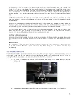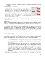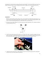
Manual Air Assist
Manual Air Assist is employed with a backsweep or cone to control air flow onto the material during laser material
processing. This feature also provides compressed air to the optics (mirrors and lenses) in the system reducing
contamination. Air assists aids in removing smoke and debris from the laser processing area and directing it to the
exhaust. It also helps reduce the heat affected zone in the material being processed and helps to prevent flame
up when processing certain materials. Use of cone vs. backsweep is dependent on the application. The
backsweep fitting is geared more toward engraving applications and the cone is geared more toward cutting
applications.
NOTE:
Air Assist can decrease frequency of cleaning for the optics but will not decrease the need for
maintenance as a whole.
Air Supply Requirements
Air Assist requires a compressed air source. ULS recommends the optional ULS Computer Controlled
Compressed Air Unit which is designed specifically for ULS laser systems. If you choose to use a different
source of compressed air, it must be capable of supplying 50 PSI max pressure and 2.0 cfm free air flow (3.2
bar and 3.2 cubic meters/hour). The air supply must be oil-free, moisture-free and particulate filtered.
CAUTION:
A contaminated air supply can cause damage to the laser system. Air or gas supply pressures
higher than 60 PSI (4.1 bar) can rupture the internal hoses. Damage to the laser system from improper air
or gas supply is not covered under warranty.
Connections to the Manual Air Assist
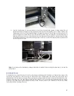
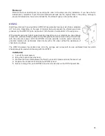
On the left rear side of the laser system you will find
the flow adjustment valve (2), a pressure gauge (1)
quick release fitting (4) and mating quick fitting (3)
which accepts a ¼” NPT fitting.
Functions of the Manual Air Assist
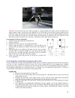
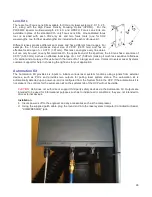
From the Quick Release Fitting (1) on the back of the
laser system, the compressed air source is directed to
the optics protection path and also to the cone or
backsweep. The optics protection path is a direct path
from the air source (1) to the #2 mirror (4) and the #3
mirror (5). The cone/backsweep path goes through the
flow adjustment valve (2), then a pressure gauge (6) and
then to the cone (3). The amount of air flowing through
the cone is adjusted using the flow adjustment valve (2)
and pressure gauge (6). The cone path protects the
focus lens and provides a downward flow directly into the beam path at the focus point of the laser beam.
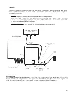
The Manual Air Assist also has a built in pressure sensors that will detect insufficient supply pressure and will
stop laser processing. An error message, “The air pressure is low or unstable” will appear on the computer
monitor, indicating that there is a problem with your supply of compressed air.
84
Summary of Contents for PLS4.75
Page 1: ...PLS User Guide PLS4 75 PLS6 75 PLS6 150D PLS6MW www ulsinc com Revision August 2012...
Page 5: ...Chapter 1 Specifications 5...
Page 8: ...Chapter 2 Safety 8...
Page 14: ...Tamper Proof Labels Safety Labels...
Page 15: ...ULS Fiber Laser Cartridge Labels 15...
Page 16: ......
Page 17: ...PLS4 Back View 17...
Page 18: ...PLS6 Front View 18...
Page 19: ......
Page 22: ...Chapter 3 Installation 22...
Page 40: ......
Page 48: ...Chapter 4 Operation 48...
Page 83: ...Chapter 5 Accessories 83...
Page 99: ...Example Connection for PNP mode Example Connection for NPN mode 99...
Page 111: ...Chapter 6 Maintenance 111...
Page 119: ...www ulsinc com...


