Installation
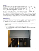
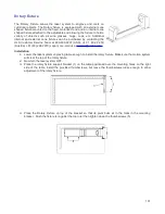
1. Place base against rulers on material processing table. Place additional pin table bases against first
base, magnets will secure them to each other when oriented correctly.
2. Place rounded pins as needed to support material to be cut.
3. Place taller squared pins to form stops to locate material if desired. Pin table photo illustrates an
example setup with support and stop pins.
4. Place material to be processed on pins.
5. Focus on top of material surface.
Direct Import (software accessory)
Direct Import is a software add-on that allows you to import PDF and DXF files directly into the Universal Control
Panel.
Installation
1. Open the System tab of the Universal Control Panel.
2. Click the “Activate” button.
3. Check the box for “Direct Import Package”
4. If you have already purchased Direct Import, click “Activate Direct Import Package” in the popup window
that appears and follow the on-screen instructions. If you have not yet purchased Direct Import, you have
the option of evaluating Direct Import for 30 days at no cost.
Operation
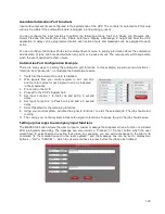
1. From the Universal Control Panel viewer tab, click the folder icon next to the job list.
2. Click “Add”
3. Select the file you would like to import. The options available to you will vary depending on whether the
file is in PDF format or DXF format.
4. This will launch a file selection dialogue box from which a PDF or DXF file can be selected to import and
convert to a job in the job queue.
Options available for PDF files:
•
All strokes as vectors – converts all vector information in the file to vector laser paths, regardless of
vector color or thickness. All vectors which are not blue in color will be converted to red “cut” vectors
when the materials database is used. If the manual tab of Laser Interface
+
is used, different settings
can be selected for each vector color.
•
Sort vectors – rearrange vector processing order to maximize processing efficiency. In most cases,
this box should be checked.
Options available for DXF files:
•
Sort vectors – rearrange vector processing order to maximize processing efficiency. In most cases,
this box should be checked.
•
Center image – places the imported DXF image at the center of the laser processing area.
•
Units – set the scale that will be used to convert DXF units into inches or centimeters. Selecting the
option marked “None (WYSIWYG)” will attempt to match the scale to that used to display the image
on the user’s monitor. The effect of “None (WYSIWYG)” setting depends on zoom levels and other
variables and may produce unpredictable results.
5. Click “Edit” to choose materials settings. Like any other job, materials settings can be changed later by
clicking the “Settings” button on the Universal Control Panel viewer tab.
6. Click OK to add the file to the job list. It may take a few moments to load the file.
7. Click “Close” to return to the viewer tab of the Universal Control Panel.
Functionality
DXF import only supports vector data. Any raster data in a DXF file will be ignored. All vector line width and
type data is ignored and all vector data is imported as solid hairline vectors. If using the materials tab in DXF
mode, red vectors will be imported as cut vectors using the vector cut laser settings in the database, blue
vectors will be imported as scribe vectors using the vector scribe laser settings in the database and all other
109
Summary of Contents for PLS4.75
Page 1: ...PLS User Guide PLS4 75 PLS6 75 PLS6 150D PLS6MW www ulsinc com Revision August 2012...
Page 5: ...Chapter 1 Specifications 5...
Page 8: ...Chapter 2 Safety 8...
Page 14: ...Tamper Proof Labels Safety Labels...
Page 15: ...ULS Fiber Laser Cartridge Labels 15...
Page 16: ......
Page 17: ...PLS4 Back View 17...
Page 18: ...PLS6 Front View 18...
Page 19: ......
Page 22: ...Chapter 3 Installation 22...
Page 40: ......
Page 48: ...Chapter 4 Operation 48...
Page 83: ...Chapter 5 Accessories 83...
Page 99: ...Example Connection for PNP mode Example Connection for NPN mode 99...
Page 111: ...Chapter 6 Maintenance 111...
Page 119: ...www ulsinc com...

