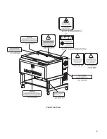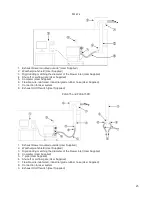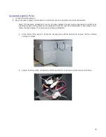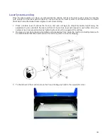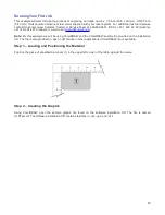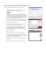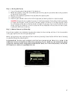
g. Locate and remove the eight screws that attach the cart to the laser system (see below).
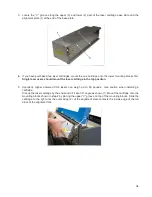
h. Lift the laser system off the cart and place the laser system front door down on a dolly for
transport.
i.
The cart and laser system can now be moved separately to the install location.
j.
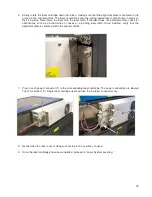
Reassemble in reverse order by placing the cart into position first and locking the casters. Then,
carefully line up the laser system and place it back on top of the cart.
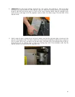
k. Bolt the laser system to the cart, re-connect the plugs and replace the access panel.
32
Summary of Contents for PLS4.75
Page 1: ...PLS User Guide PLS4 75 PLS6 75 PLS6 150D PLS6MW www ulsinc com Revision August 2012...
Page 5: ...Chapter 1 Specifications 5...
Page 8: ...Chapter 2 Safety 8...
Page 14: ...Tamper Proof Labels Safety Labels...
Page 15: ...ULS Fiber Laser Cartridge Labels 15...
Page 16: ......
Page 17: ...PLS4 Back View 17...
Page 18: ...PLS6 Front View 18...
Page 19: ......
Page 22: ...Chapter 3 Installation 22...
Page 40: ......
Page 48: ...Chapter 4 Operation 48...
Page 83: ...Chapter 5 Accessories 83...
Page 99: ...Example Connection for PNP mode Example Connection for NPN mode 99...
Page 111: ...Chapter 6 Maintenance 111...
Page 119: ...www ulsinc com...

