background image

7-2

Laser Printer 300 Series

Chapt

er

7

S

pec

if

ic

at

ions

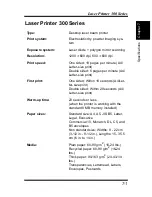
Paper feeding:

Tray 1(Multipurpose tray), Manual feed
tray, Tray 2 (500-sheet second cas-
sette)(option), Tray 3 (500-sheet third
cassette)(option)

Input capacity:

Tray 1 (Multipurpose tray): 250 sheets
Tray 2 (Second cassette) (option): 500
sheets
Tray 3 (Third cassette) (option): 500
sheets

Output capacity:

250 sheets (face-down)

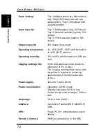
Operating temperature:

10 - 35

°

C (50

°

F - 95

°

F) with fluctuation

of 10

°

C

 (

18

°

F) per hour

Operating humidity:

15% to 85% with fluctuation of 20% per
hour

Imaging cartridge life:

9,000 A4/Letter-size prints (black-to-
white ratio of 5% or less)
The imaging cartridge that comes with
the printer is capable of producing
approximately 5,000 A4/Letter-size
prints.)

Power supply:

220-240 V at 50–60 Hz

Power consumption:

Operating: 820 W or less
Standby (average): 60 W or less
Power saving mode (average): 30 W or
less

Amperage:

3.5 A or less (220 V)

Interface:

Centronics Parallel (IEEE 1284/ECP)
USB

CPU:

Power PC 401 embedded processor/
66MHz

Standard memory:

8 MB (expandable up to 104 MB)

Summary of Contents for LP 218

Page 1: ...INSTRUCTION HANDBOOK LP 218 Laser Printer 300 Series ...

Page 2: ...03 mW at laser aperture of the print head unit Wavelength 770 810 nm This product employs Class IIIb Laser Diode that emits an invisible laser beam Laser Diode and Scanning Polygon Mirror are incorporated in the print head unit The print head unit is not a field service item Therefore the print head unit should not be opened under any circum stance Laser Safety This printer is certified as a Class...

Page 3: ...76 Compliance is mandatory for products marketed in the United States The label shown below indicates com pliance with the CDRH regulations and must be attached to laser prod ucts marketed in the United States Laser Safety Label Caution Use of controls adjustments or performance of procedures other than those specified in this manual may result in hazardous radia tion exposure ...

Page 4: ...iii Foreword Caution Laser Caution Label This is a semiconductor laser The maximum power of the laser diode is 5 mW and the wavelength is 770 810 nm ...

Page 5: ...r 300 Series Options Second Paper Cassette Unit Third Paper Cassette Unit Duplex Unit Expansion memory Maximum 96MB This device complies with Part 15 of the FCC Rules Operation is subject to the following conditions 1 this device may not cause harmful interference and 2 this device must accept any interference received including interference that may cause undesired operation ...

Page 6: ...nd on the user is encouraged to try to correct the interface by one or more of the follow ing measures Reorient or relocate the receiving antenna Increase the separation between the equipment and the receiver Connect the equipment into an outlet on a circuit different from that to which the receiver is connected Consult the dealer or an experienced radio TV technician for help This device must be ...

Page 7: ... During printer operation a small quantity of ozone is released This amount is not large enough to harm anyone adversely However be sure the room where the machine is being used has adequate ventila tion especially if you are printing a high volume of materials or if the machine is being used continuously over a long period The design and production of this unit conform to FCC regulations and any ...

Page 8: ...d for later ref erence The contents of this manual are subject to change without notice Should there be any discrepancy between the printed materials and the electronic based resources provided with your printer please refer to the printed materials as your primary resource Trademark Acknowledgments PCL is a registered trademark of Hewlett Packard Company Centronics is a registered trademark of Ce...

Page 9: ...viii Foreword ...

Page 10: ... a Location for the Printer 2 1 Operating Environment 2 5 Printer 2 5 Printer Supplies 2 7 Unpacking the Printer 2 8 Installing the Face Down Tray 2 10 Installing Tray 1 2 11 Connecting the Power Cord 2 12 Second Third Paper Cassette Unit 2 20 Expansion Memory 2 30 Using the Printer 3 1 Print Configuration Page 3 1 Form Feed 3 1 Type 3 2 Paper Type 3 18 Paper Size 3 18 ...

Page 11: ...g the PCL Printer Driver Under Windows 95 4 17 To Install the PCL Printer Driver Using Plug and Play 4 17 To Install the PCL Printer Driver Using the Add Printer Wizard 4 19 Installing the PCL Printer Driver Under Windows 98 Windows Me 4 21 To Install the PCL Printer Driver Using Plug and Play Under Windows 98 4 21 To Install the PCL Printer Driver Using Plug and Play Under Windows Me 4 23 To Inst...

Page 12: ...d 4 33 Installing the Laser Printer 300 Series Utilities4 36 Using the PCL Printer Driver 4 38 Displaying the PCL Printer Driver Setup Dialog 4 38 Common Buttons 4 42 Setup 4 43 Paper 4 51 Quality 4 55 Device Options Setting 4 58 Using the Status Display 4 59 Starting Up the Status Display 4 59 Using the Status Display 4 61 Using the Control Panel 4 63 Starting Up the Control Panel 4 63 Using the ...

Page 13: ...ance 5 1 To Replace the Imaging Cartridge 5 2 Cleaning the Outside of the Printer 5 8 Cleaning the Paper Feed Roller 5 9 Troubleshooting 6 1 Clearing a Paper Misfeed 6 1 Inside the Printer 6 1 Face Down Tray 6 6 Tray 1 6 6 Manual Feed Tray 6 8 Second Third Paper Cassette Unit Option 6 9 Duplex Unit Option 6 10 Print Quality Problems 6 12 No Output 6 17 USB Connection Problems 6 19 Is the computer ...

Page 14: ...xii Contents Was the computer correctly set up 6 20 Indicator Lights Printer Messages 6 30 Indicator Light Patterns 6 30 Specifications 7 1 Parallel Interface 7 7 ...

Page 15: ...xiii Contents ...

Page 16: ...MEMO ...

Page 17: ...xv Contents ...

Page 18: ...Chapter 1 Introduction 1 1Chapter Introduction ...

Page 19: ...Chapter 1 Introduction ...

Page 20: ...ize office Fast 18 page per minute print speed for quick output 1200 600 dpi resolution for superior print quality PCL 6 emulation for powerful printer language support 66 MHz RISC processor for high performance printing 8 MB of memory standard USB interface built in Operating System Windows 95 Windows 98 Windows Me Windows NT 4 0 Windows 2000 ...

Page 21: ...Chapter 1 Introduction Printer Parts and Accessories Printer Control panel Face down tray Paper guide Tray 1 Multipurpose tray Top cover release button Power switch USB interface connector Power cord socket Parallel interface connector ...

Page 22: ...1 3 Chapter 1 Introduction Printer Parts and Accessories Fusing unit Paper guide Manual feed tray Tray cover Top cover Image transfer roller Imaging cartridge ...

Page 23: ... Parts and Accessories Chapter 1 Introduction Options Cassette cover Tray 2 500 sheet second cassette Cassette cover Tray 3 500 sheet third cassette Third paper cassette unit Second paper cassette unit Duplex unit ...

Page 24: ... Note ex You can find out details of the printer s status by checking the informa tion that appears on your computer screen see Starting Up the Status Display on page 4 59 See Indicator Lights Printer Messages on page 6 30 for information about how the control panel indicators indicate the current status of the printer Paper amber indicator Error red indicator Ready green indicator Panel button Pr...

Page 25: ...Chapter 1 Introduction Panel Button The panel button can be used to perform various operations according to the status of the printer Print configuration page Form feed For details see Using the Panel Button on page 3 1 ...

Page 26: ...Chapter 2 Setting Up 2 2Chapter Setting Up ...

Page 27: ...Chapter 2 Setting Up ...

Page 28: ...r other organic gasses being generated in the area The power outlet you plan to connect to for power should be nearby and unobstructed Make sure that the printer is not exposed to direct sunlight Avoid areas in the direct airflow of air conditioners heaters or ven tilators and areas subjected to temperature and humidity extremes Choose a sturdy level surface where the printer will not be exposed t...

Page 29: ...ements Be sure to provide space around the printer as indicated below to ensure easier printer operation paper and toner replacement and main tenance 33 in 84 cm 11 3 4 in 30 cm 24 3 4 in 63 cm 4 in 10 cm 11 3 4 in 30 cm 40 1 2 in 103 cm 6 in 15 cm 23 1 2 in 60 cm ...

Page 30: ...outlet should be located near the printer and be easily accessible so you can unplug the power cord immediately should any problem occur Make sure the outlet you use is visible and not hidden behind the printer or any other object If any other electrical equipment is plugged into the same outlet make sure that the capacity of the outlet is not exceeded If you use an extension cord make sure its ca...

Page 31: ...trical shock To ground the printer connect the grounding wire to the ground terminal of the electrical outlet you are plugging in to or to a grounding contact that complies with local electrical standards in your area Note Never connect the grounding wire to a gas pipe the grounding wire for a telephone or to a water pipe ...

Page 32: ... generate mag netic forces near the printer When unplugging the power cord always grasp the plug and never pull on the cord A damaged cord creates the danger of fire or elec trical shock Never touch the power cord when your hands are wet Doing so cre ates the danger of electrical shock Always unplug the power cord before moving the printer Failure to do so can damage the power cord creating the da...

Page 33: ...r electrical shock can occur should water or liquid come into contact with the printer Should liquid or any piece of metal accidently get inside the printer immediately turn it off unplug the power cord and contact cus tomer support Failure to take this immediate action creates the dan ger of fire or electrical shock Whenever the printer emits unusually high amounts of heat smoke an unusual odor o...

Page 34: ...rtridge that is expressly specified for this printer Keep supplies out of the reach of children Should your hands become soiled with toner immediately wash them with soap and water Caution Placer l imprimante dans une pièce largement ventilée Une quantité d ozone négligable est dégagée pendant le fonctionne ment de l imprimante quand celle ci est utilisée normalement Cependant une odeur désagréabl...

Page 35: ...low out of the carton Caution Note After unpacking keep all packing materials out of the reach of children Keep all the boxes and packing materials that the printer comes in for later use when transporting the printer 1 Face down tray 2 Printer 3 Accessories Installation Guide CD ROM Power cord 4 Tray 1 1 2 3 4 ...

Page 36: ...r 2 Setting Up Installing 2 Remove the plastic bag and peel off the shipping tape from the printer 3 Pull out the two cushions from the paper feed inlet 4 Pull out the plastic lead strip from the paper feed inlet ...

Page 37: ...item s see Options on page 2 20 Installing the Face Down Tray With both hands gently bend the face down tray inwards and insert one of its tabs into its holder on the upper portion of the printer Con tinue to bend the face down tray so that it curves enough for the sec ond tab to fit into its holder and release the tray into position ...

Page 38: ...tting Up Installing Installing Tray 1 1 Using the left and right slots in the printer as guides gently push Tray 1 until it cannot be inserted any further as shown in the illustration 2 Attach the tray cover onto Tray 1 ...

Page 39: ... printer according to the following instructions Connecting the Power Cord 1 Make sure that the power switch is in the Off position 2 Connect one end of the power cord that comes with the printer to the power cord socket Plug the other end into a power outlet ...

Page 40: ...2 13 Chapter 2 Setting Up Setting Up Loading Paper 1 Remove the tray cover from Tray 1 2 Open all three paper guides ...

Page 41: ...2 14 Setting Up Chapter 2 Setting Up 3 Place a stack of paper in the center of Tray 1 Secure the stack by adjusting the paper guides 4 Replace the tray cover onto Tray 1 ...

Page 42: ...nly the Ready indicator remains lit indicating that the printer is ready to print Note The printer automatically enters a power saving mode after a set period of time in which it does not receive a print command from the computer The default setting is 15 minutes however the time period can be changed using the control panel see Using the Control Panel on page 4 63 Whenever the printer receives a ...

Page 43: ...sure that both the Paper and Error indicators are off and the Ready indicator is on This indicates there is no existing error condition and no data remaining to be printed 3 Briefly press the panel button to start the configuration page print operation See No Output on page 6 17 for information on what to do if the con figuration page does not print when you press the panel button Panel button Fac...

Page 44: ...2 17 Chapter 2 Setting Up Setting Up Sample Configuration Page ...

Page 45: ... parallel inter face connector on the back of the printer Secure the interface cable using the two clips on the parallel interface connector Always use a shielded interface cable Use of an unshielded cable can result in radio interference with data You must purchase an IEEE 1284 type B cable for connection between the printer and a computer For detailed specifications of the interface cable see In...

Page 46: ...nnect one end of the interface cable to the USB port of the computer 5 Connect the other end of the interface cable to the USB interface connector on the back of the printer Note This printer cannot be connected with a USB cable to a computer run ning Windows 95 or Windows NT 4 0 If Windows does not detect the new device leave the printer on unplug both ends of the USB interface cable and then rec...

Page 47: ...ette that can hold up to 500 sheets of Letter size paper called Tray 2 Tray 3 The same unit can accommodate a variety of other paper trays as well A4 JIS B5 Legal Executive The second and third paper cassette unit are interchangeable and can increase paperholding capacity to 1 000 sheets when installed together Contact your dealer to find out how you can add these trays to increase the capabilitie...

Page 48: ...Setting Up Options Space Requirements 84 cm 33 in 30 cm 11 3 4 in 75 cm 29 1 2 in 87 cm 34 1 4 in 10 cm 4 in 30 cm 11 3 4 in 103 cm 40 1 2 in 15 cm 6 in 60 cm 23 1 2 in when equipped with the third paper cassette unit ...

Page 49: ...d Paper Cassette Unit 1 Turn off the printer and then disconnect the power cord and interface cable from the printer 2 Remove the paper cassette unit and the cassette from their packaging including the protective tape used to hold the various components in place ...

Page 50: ...s located underneath the printer Second paper cassette unit Third paper cassette unit Note 4 Load paper onto Tray 2 Tray 3 See Loading Paper onto Tray 2 Tray 3 Option on page 3 13 for details The printer weighs approximately 18 kg 39 7 lbs with the optional second paper cassette unit installed Two people are recommended to lift it when necessary ...

Page 51: ...2 24 Options Chapter 2 Setting Up 5 Replace the cassette cover and insert Tray 2 or Tray 3 into the paper cassette unit Tray 2 Tray 3 ...

Page 52: ...ng On the Printer on page 2 15 7 Generate a configuration page to verify that Tray 2 or Tray 3 is listed under Printer Configuration item See Testing the Printer on page 2 16 Be sure to use both hands whenever the cassette is removed from or inserted into the paper cassette unit PRINTER CONFIGURATION Tray 2 Installed Tray 3 Installed Duplex Unit Not Installed ...

Page 53: ...the paper through the printer software For more information refer to Duplex Printing on page 3 17 Take the duplex unit out of the shipping box Remove the plastic bag and all shipping materials Turn the printer off and then disconnect the power cord and inter face cable from the printer Space Requirements 84 cm 33 in 30 cm 11 3 4 in 63 cm 24 3 4 in 10 cm 4 in 30 cm 11 3 4 in 118 cm 46 1 2 in 30 cm ...

Page 54: ...nect the power cord and interface cable from the printer 2 Remove the duplex unit from the packaging including the pro tective tape used to hold the various components in place 3 With a screwdriver or similar instrument remove the flat clip that is attached to the back of the main unit of the printer ...

Page 55: ...lign the L shaped duplex unit to the back of the main unit of the printer so that the bottom of the L is inside of the opening at the bottom of the printer Note Make sure that the connector of the unit is inserted into the printer securely ...

Page 56: ...then turn the printer on See Connecting the Power Cord on page 2 12 See Turning On the Printer on page 2 15 7 Generate a configuration page to verify that duplex unit is listed under the Printer Configuration item See Testing the Printer on page 2 16 Hold up the duplex unit with your hand during installation until it is secured to the printer with the screws PRINTER CONFIGURATION Tray 2 Not Instal...

Page 57: ...ion memory SIMM into the printer SIMMs are available from most computer retailers Installing the Expansion Memory Warning 1 Turn off the printer and then disconnect the power cord and interface cable from the printer 2 Remove the expansion memory SIMM from its packaging 3 Close the face down tray and press the top cover release but ton to open the top cover Electric shock hazard Do not remove any ...

Page 58: ... Clips secure the exterior side cover from the inside of the printer Gently maneuver the exterior side cover until the clips release see illustration 6 With the exterior side cover removed the internal side cover of the printer is exposed With the screwdriver loosen and remove the four screws that secure the internal side cover ...

Page 59: ...ose the main circuit Caution 8 Being careful not to touch the connection points along the edge of the expansion memory insert the expansion memory into one of the available sockets on the main circuit Do not touch any part of the main circuit inside the printer SIMM sockets ...

Page 60: ...etting Up Options Insert the expansion memory at an angle as shown and gently swing it into the socket Apply pressure until the expansion memory locks into place 9 Replace the internal side cover using the four screws ...

Page 61: ... correctly shows the increase in memory capacity If it does not repeat the above steps making sure that the expansion memory is installed correctly Note To release the expansion memory from the socket push out on the taps on each side of the socket Once the expansion memory has been installed be sure to reset the Printer Memory Setting to reflect the new memory capacity see Using the Control Panel...

Page 62: ...Chapter 3 Using the Printer 3 3Chapter Using the Printer ...

Page 63: ...Chapter 3 Using the Printer ...

Page 64: ...nt Configuration Page Use the following procedure whenever you want to configuration for printer Press the panel button while printer is idle without any errors and job requests See Testing the Printer on page 2 16 for details Form Feed Use the following procedure whenever a print job is canceled due to a memory overflow Press the panel button to perform a form feed Panel button ...

Page 65: ...es of paper Paper Source Manual Feed Tray Tray 1 Tray 2 Tray 3 Paper Type Plain Paper weight 60 90 g m2 16 24 lbs Recycled Paper weight 60 90 g m2 16 24 lbs Special Paper Transparency Sheet None Labels None Letterhead None Envelopes None Thick Paper weight 90 163 g m2 24 to 43 1 4 lbs None Special paper is not supported for duplex printing ...

Page 66: ...with this printer 2 Letter is standard cassette size for the second third paper cassette unit This printer is designed to print on only the following sizes of paper Paper Source Manual Feed Tray Tray 1 Tray 2 Tray 3 1 Paper Size Standard Size A4 210 mm 297 mm A5 148 mm 210 mm None JIS B5 182 mm 257 mm Legal 8 1 2 in 14 in Letter 8 1 2 in 11 in 2 Executive 7 1 4 in 10 1 2 in ...

Page 67: ...Source Manual Feed Tray Tray 1 Tray 2 Tray 3 Paper Size Envelope and Cus tom Size Env DL 110 mm 220 mm None Env C5 162 mm 229 mm None Env B5 176 mm 250 mm None Env Com10 4 1 8 in 9 1 2 in None Env Monarch 3 7 8 in 7 1 2 in None Custom Size 3 1 2 in to 8 1 2 in 6 in to 14 in None ...

Page 68: ... paper heat sensitive paper and pressure sensitive paper Sheets of various sizes Paper not cut on right angles Paper bound by glue staples or clips Paper affixed with labels which are easy to peel Post cards that are warped or bent Envelopes should meet the following requirement Sharp folds and edges General mailing envelopes without seals on the glued portion Having flags the full width of the en...

Page 69: ...rinting Paper Chapter 3 Using the Printer Printable Area This printer is designed to print on paper with a 4 mm 0 16 in margin on all sides 4 mm 0 16 in 4 mm 0 16 in 4 mm 0 16 in 4 mm 0 16 in Printable area ...

Page 70: ... Tray 3 as a secondary third paper source See Second Third Paper Cassette Unit on page 2 20 for details on using this tray unit Whenever you are using special size paper be sure to use the printer driver installed on the computer to specify the printing area You may experience some variation in print quality when using special size paper Always remember that paper storage conditions greatly affect...

Page 71: ...sing the Printer Loading Paper onto Tray 1 You can load up to 250 sheets of standard paper onto Tray 1 See Printing Paper on page 3 2 for details on paper sizes and types 1 Remove the tray cover from Tray 1 2 Open the paper guides ...

Page 72: ...nd the right sides of the paper stack are secure Note 4 Replace the tray cover onto Tray 1 A maximum level mark on the paper guide shows how high you can stack paper on Tray 1 Make sure that paper is stacked no higher than this mark Do not load additional paper until the paper currently loaded onto Tray 1 is completely used Maximum level mark ...

Page 73: ...Manual Feed Tray 1 Make sure that the tray cover is properly attached to Tray 1 2 Open the paper guides 3 Insert the sheet of paper into the manual feed tray with the side to be printed facing up Note Insert only one sheet of paper at a time when feeding manually ...

Page 74: ...inter Make sure that all edges are creased sharply and that all flaps are folded correctly Do not use envelopes that are self adhesive Use only envelopes that have standard sealing that sticks after it is moistened Use envelopes of which flaps run the entire length of the envelope Enve lopes that seal at one end will not feed properly Do not use envelopes that have a window Such envelopes can seri...

Page 75: ...e side to be printed facing up on the tray The flap of the envelope should be facing down and to the left Note 2 Make sure that the envelope is placed in the center of the tray and that it is secured by the paper guides Insert only one envelope at a time when feeding manually ...

Page 76: ... unit Make sure that the Tray 2 Tray 3 for the proper size of paper to be used for printing has been installed into the second third paper cassette unit See Second Third Paper Cassette Unit on page 2 20 for instructions on inserting and removing the Tray 2 Tray 3 into and from the second third paper cassette unit To remove Tray 2 Tray 3 from the unit pull it out as far as it will go without force ...

Page 77: ...3 14 Loading Paper Chapter 3 Using the Printer 2 Remove the cassette cover from Tray 2 Tray 3 3 Press down on the paper lifting plate located inside of Tray 2 Tray 3 until it locks ...

Page 78: ...pped is still facing up Note A maximum level mark inside the inlet of Tray 2 Tray 3 shows how high you can stack paper on Tray 2 Tray 3 Make sure that paper is stacked no higher than this mark Tray 2 Tray 3 does not support landscape oriented paper feeding Do not load additional paper until all the paper currently on Tray 2 Tray 3 is completely used up Maximum level mark ...

Page 79: ...3 16 Loading Paper Chapter 3 Using the Printer 5 Replace the cassette cover and insert Tray 2 Tray 3 into the second third paper cassette unit Tray 2 Tray 3 ...

Page 80: ... data on both sides of a sheet of paper Installation of the optional duplex unit is required to perform duplex printing You can choose either Bind Long Edge or Bind Short Edge when gen erating duplex documents Bind Long Edge Bind Short Edge Portrait Landscape A A A A Portrait Landscape A A A A ...

Page 81: ...ber the following points when generating duplex documents The size of both original documents that will be used to make one duplex document must be the same The original document that is loaded first into the duplex unit will be output face down Do not use special paper transparencies labels envelopes letterhead and thick paper for duplex printing The Long Edge Binding setting of the printer drive...

Page 82: ...Chapter 4 PCL Printer Driver 4 4Chapter PCL Printer Driver ...

Page 83: ...Chapter 4 PCL Printer Driver ...

Page 84: ...bles proper printing For detailed instructions on installing the PCL Printer Driver refer to page 4 17 4 21 4 27 or 4 30 Status Display This program displays information about the current status of the computer s local printer For detailed instructions on installing the Status Display refer to page 4 36 Control Panel This program displays the current settings of the computer s local printer You ca...

Page 85: ...ocessor recommended CD ROM drive I O Interface IEEE 1284 type B parallel USB not available with Windows 95 or Windows NT 4 0 Memory At least 8MB of PC RAM Free Disk Space Approximately 5MB for files Important When connecting the printer to the computer with a USB cable be sure to read the section Installing the USB Device Driver for the Laser Printer 300 Series on page 4 3 If the printer is not be...

Page 86: ...ver according to the fol lowing instructions before installing the printer driver This printer cannot be connected with a USB cable to a computer run ning Windows 95 or Windows NT 4 0 To Install the USB Device Driver Under Windows 98 1 Turn on your computer and start up Windows 98 2 Turn on the printer 3 Check that Windows 98 has finished starting up and that the printer is ready 4 Insert the Prin...

Page 87: ...display the Add New Hardware Wizard dialog 6 Click Next to display the next dialog 7 Check the Search for the best driver for your device Rec ommended option button and then click Next 8 When the next dialog appears check the Specify a location box and then click Browse 9 Browse the CD ROM and navigate to English usb Then click OK 10 Follow the instructions that appear on your computer screen to c...

Page 88: ...ollowing dialog appears click Finish to finish the installation This completes the installation of the USB device driver for the Laser Printer 300 Series printer 12 When the Add Printer Wizard dialog appears continue with the procedure in To Install the PCL Printer Driver Using the Add Printer Wizard on page 4 25 ...

Page 89: ...k that Windows Me has finished starting up and that the printer is ready 4 Insert the Printer Driver CD ROM that comes with your printer into your computer s CD ROM drive 5 Connect the printer to the computer with the USB cable For more details refer to Connecting to a Computer on page 2 18 to display the Add New Hardware Wizard dialog 6 Check the Specify the location of the driver Advanced option...

Page 90: ...eries 7 Check the Search for the best driver for your device Rec ommended option button check the Specify a location box and then click Browse 8 Browse the CD ROM and navigate to English usb Then click OK 9 Follow the instructions that appear on your computer screen to complete the installation ...

Page 91: ...he following dialog appears click Finish to finish the installation This completes the installation of the USB device driver for the Laser Printer 300 Series 11 When the Add Printer Wizard dialog appears continue with the procedure in To Install the PCL Printer Driver Using the Add Printer Wizard on page 4 25 ...

Page 92: ...n the operating system In order to activate all functions of the Laser Printer 300 Series the USB device driver must be installed Install the USB device driver for the Laser Printer 300 Series according to the following procedure 1 Turn on your computer and start up Windows 2000 2 Turn on the printer 3 Check that Windows 2000 has finished starting up and that the printer is ready 4 Insert the Prin...

Page 93: ...er See To Install the PCL Printer Driver Using Plug and Play on page 4 30 After installing the printer driver install the USB device driver for the Laser Printer 300 Series as described below 7 Right click the My Computer icon on the desktop and then click Properties in the shortcut menu that appears The System Properties dialog appears 8 Click the Hardware tab of the System Properties dialog and ...

Page 94: ...4 11 Chapter 4 PCL Printer Driver Installing the USB Device Driver for the Laser Printer 300 Series 10 Click the Driver tab of the USB Printing Support Properties dia log and then click Update Driver ...

Page 95: ...uitable driver for my device recom mended option button and then click Next 13 When the next dialog appears check the Specify a location box and then click Next 14 Click Browse 15 Browse the CD ROM and navigate to English usb Then click Open 16 Click OK and then click Next 17 Follow the instructions that appear on your computer screen to complete the installation ...

Page 96: ... Chapter 4 PCL Printer Driver Installing the USB Device Driver for the Laser Printer 300 Series 18 When the following dialog appears click Cancel Note Be sure to click Cancel to stop the Add Printer Wizard ...

Page 97: ...n the following dialog appears click Finish to finish install ing the USB device driver Continue with this procedure to set the printer port 20 Click Start point to Settings and then click Printers to display the Printers dialog 21 In the Printers dialog click the Laser Printer 300 Series PCL6 printer icon ...

Page 98: ...Driver Installing the USB Device Driver for the Laser Printer 300 Series 22 Select Properties from the File menu 23 In the Properties dialog click the Ports tab and then select USB 001 Laser Printer 300 Series from the ports list ...

Page 99: ...r Offline in the File menu to remove the check 26 Click the General tab of the Properties dialog and then click Print Test Page Check that the test page is correctly printed by the printer This completes the installation and setting of the USB device driver Remove the check for the port with Virtual printer port for USB listed under Description and then select the port with Laser Printer 300 Serie...

Page 100: ... Using Plug and Play 1 After connecting the printer to your computer with the parallel cable turn on the printer 2 Turn on your computer and start up Windows 95 The Update Device Driver Wizard dialog appears on the dis play 3 Insert the Printer Driver CD ROM that comes with your printer into your computer s CD ROM drive and then click Next 4 Click the Other Location button type D English PCL6Drive...

Page 101: ...Check that the Laser Printer 300 Series PCL6 printer icon is displayed in the Printers dialog To display the Printers dialog click Start point to Settings and then click Printers 7 Eject the CD ROM from your computer s CD ROM drive This completes the installation of printer driver An opportunity to designate a name for the printer will be pro vided during the installation procedure ...

Page 102: ...that comes with your printer into your computer s CD ROM drive 3 Click Start point to Settings and then click Printers 4 Double click the Add Printer icon 5 Click Next 6 Select Local Printer 7 Click Next 8 Click Have Disk 9 Browse the Printer Driver CD ROM and navigate to English PCL6Driver W95 Next click OK 10 Click OK and then click Next 11 Follow the instructions that appear on your computer sc...

Page 103: ...er Windows 95 Chapter 4 PCL Printer Driver 12 Check that the Laser Printer 300 Series PCL6 printer icon is displayed in the Printers dialog 13 Eject the CD ROM from your computer s CD ROM drive This completes the installation of printer driver ...

Page 104: ...ation with a parallel connection is described below For details on the installation with a USB connection see To Install the USB Device Driver Under Windows 98 on page 4 3 1 After connecting the printer to your computer with the parallel cable turn on the printer 2 Turn on your computer and start up Windows 98 The Add New Hardware Wizard dialog appears on the display 3 Insert the Printer Driver CD...

Page 105: ... instructions that appear on your computer screen to complete the installation Note 9 Check that the Laser Printer 300 Series PCL6 printer icon is displayed in the Printers dialog To display the Printers dialog click Start point to Settings and then click Printers 10 Eject the CD ROM from your computer s CD ROM drive This completes the installation of printer driver An opportunity to designate a n...

Page 106: ...e on page 4 6 1 After connecting the printer to your computer with the parallel cable turn on the printer 2 Turn on your computer and start up Windows Me The Add New Hardware Wizard dialog appears on the display 3 Insert the Printer Driver CD ROM that comes with your printer into your computer s CD ROM drive and click the Specify the location of the driver Advanced button Then click Next 4 Check t...

Page 107: ...ote 8 Check that the Laser Printer 300 Series PCL6 printer icon is displayed in the Printers dialog To display the Printers dialog click Start point to Settings and then click Printers 9 Eject the CD ROM from your computer s CD ROM drive This completes the installation of printer driver An opportunity to designate a name for the printer will be pro vided during the installation procedure ...

Page 108: ... Driver Using the Add Printer Wizard 1 Turn on your computer and start up Windows 98 or Windows Me 2 Insert the Printer Driver CD ROM that comes with your printer into your computer s CD ROM drive 3 Click Start point to Settings and then click Printers 4 Double click the Add Printer icon 5 Click Next 6 Select Local Printer ...

Page 109: ... you selected Local Printer in step 6 specify the desired port If a parallel connection is being used select LPTX X 1 2 etc If a USB connection is being used select USB 001 Then click OK 12 Follow the instructions that appear on your computer screen to complete the installation 13 Check that the Laser Printer 300 Series PCL6 printer icon is displayed in the Printers dialog 14 Eject the CD ROM from...

Page 110: ...g the Laser Printer 300 Series PCL printer driver on a computer running Windows NT 4 0 To Install the PCL Printer Driver Using the Add Printer Wizard 1 Turn on your computer and start up Windows NT 4 0 2 Insert the Printer Driver CD ROM that comes with your printer into your computer s CD ROM drive 3 Click Start point to Settings and then click Printers 4 Double click the Add Printer icon ...

Page 111: ...xt 7 Specify the ports you want to use and the click Next 8 Click Have Disk and then click Browse 9 Browse the Printer Driver CD ROM and navigate to English PCL6Driver W98Nt2K WinNT4 Next click Open 10 Click OK and then click Next 11 Follow the instructions that appear on your computer screen to complete the installation ...

Page 112: ... the PCL Printer Driver Under Windows NT 4 0 12 Check that the Laser Printer 300 Series PCL6 printer icon is displayed in the Printers dialog 13 Eject the CD ROM from your computer s CD ROM drive This completes the installation of printer driver ...

Page 113: ...ng the Laser Printer 300 Series PCL printer driver on a computer running Windows 2000 To Install the PCL Printer Driver Using Plug and Play For a parallel connection 1 After connecting the printer to your computer turn on the printer 2 Turn on your computer and start up Windows 2000 The Found New Hardware Wizard dialog appears on the dis play Continue with step 5 on the following page ...

Page 114: ...er to the computer with the USB cable For more details refer to Connecting to a Computer on page 2 18 to display the Found New Hardware Wizard dialog 5 Insert the Printer Driver CD ROM that comes with your printer into your computer s CD ROM drive and then click Next 6 Check the Display a list of the known drivers for this device so that I can choose a specific driver option button and then click ...

Page 115: ...that the Laser Printer 300 Series PCL6 printer icon is displayed in the Printers dialog To display the Printers dialog click Start point to Settings and then click Printers 13 Eject the CD ROM from your computer s CD ROM drive This completes the installation of printer driver Note With a USB connection the USB device driver for the Laser Printer 300 Series must be installed Leave the CD ROM in the...

Page 116: ...e PCL Printer Driver Using the Add Printer Wizard 1 Turn on your computer and start up Windows 2000 2 Insert the Printer Driver CD ROM that comes with your printer into your computer s CD ROM drive 3 Click Start point to Settings and then click Printers 4 Double click the Add Printer icon 5 Click Next ...

Page 117: ...lling the PCL Printer Driver Under Windows 2000 Chapter 4 PCL Printer Driver 6 Select Local printer Note If Local Printer is selected do not check the Automatically detect and install my plug and play printer box ...

Page 118: ...being used select USB 001 9 Click Have Disk and then click Browse 10 Browse the Printer Driver CD ROM and navigate to English PCL6Driver W98Nt2K Next click Open 11 Click OK and then click Next 12 Follow the instructions that appear on your computer screen to complete the installation 13 Check that the Laser Printer 300 Series PCL6 printer icon is displayed in the Printers dialog 14 Eject the CD RO...

Page 119: ...r 300 Series Utilities 1 Insert the Printer Driver CD ROM that comes with your printer into your computer s CD ROM drive 2 Double click the My Computer icon on the desktop and then double click the CD ROM drive icon 3 Open the English UtilitySetup folder on the CD ROM and then double click the Setup exe file 4 Follow the instructions that appear on your computer screen to complete the installation...

Page 120: ...tatus Display starts up automatically when Windows is started To start up Status Display automatically check the Setup to Start Status Display automatically box 6 After the installation is completed the following dialog appears on the desktop of the computer 7 Eject the CD ROM from your computer s CD ROM drive This completes the installation of the Utilities ...

Page 121: ...erties dialog box The settings you make with the Properties dialog box become the default settings for the Laser Printer 300 Series PCL6 Printer Driver Displaying the PCL Printer Driver Setup Dialog To Display the PCL Printer Driver Setup Dialog Under Windows 95 Windows 98 Windows Me 1 Click Start point to Settings and then click Printers to display the Printers dialog 2 In the Printers dialog cli...

Page 122: ...4 39 Chapter 4 PCL Printer Driver Using the PCL Printer Driver 4 On the 32 bit SuperDriver Setup tab of the Properties dia log the following window appears ...

Page 123: ...er Driver To Display the PCL Printer Driver Setup Dialog Under Windows NT 4 0 Windows 2000 1 Click Start point to Settings and then click Printers to display the Printers dialog 2 In the Printers dialog click the Laser Printer 300 Series PLC6 printer icon ...

Page 124: ...ter Driver Using the PCL Printer Driver 3 For Windows NT 4 0 select Document Defaults from the File menu For Windows 2000 select Printing Preference from the File menu The following window appears Windows NT 4 0 Windows 2000 ...

Page 125: ...ox Help Click to view online help Note Easy Set To save the current settings click Save Afterward the saved settings can be selected from the drop down list Select the Default from the drop down list to reset the functions of the tab to their original values Page Layout Check this option button to display a sample of the page layout in the figure area Printer Figure Check this option button to dis...

Page 126: ...single page Click on the drop down list to view the possible selections Off This default setting specifies one document per sheet of paper 2 up This setting will print two documents onto one sheet of paper 4 up This setting will print four documents onto one sheet of paper 6 up This setting will print six documents onto one sheet of paper 9 up This setting will print nine documents onto one sheet ...

Page 127: ...yle to open a dialog that will allow you to spec ify the order in which N up documents are placed on the page There are four patterns to choose from horizontal ascending horizontal descending vertical ascending and vertical descending Note The Scaling Fit to Paper and Booklet features of the printer driver can not be used when printing N up documents see page 4 48 page 4 53 ...

Page 128: ...en entered into the printer s memory You can add and delete watermarks from this list through the Watermark pop up dialog Watermarks can be specified to appear on the first page only of a multi page document by clicking the 1st Page only box Otherwise a water mark that is specified to appear will be placed on every page of the multi page document Watermark Pop up dialog To open the dialog click th...

Page 129: ...Name The name that you wish to use to identify the watermark in the Watermark list is entered here String The contents of the watermark that you wish to create are entered here Font Type Face The typeface of the watermark is specified here Size The character size point of the watermark is specified here Style These settings can be used to specify the style of the watermark s font Shading The densi...

Page 130: ...the watermark from the drop down list User Setting If User Setting was selected from the drop down list specify the angle of the watermark here Position Center Check here to position the watermark in the center of the document User Setting Check here to specify the position of the water mark Horizontal Adjust this value to move the watermark to the desired horizontal location in the document Verti...

Page 131: ...ments in a calendar style format Long Edge Binding Allows you to print portrait oriented documents in a book style format Booklet Left Binding Allows you to print documents that are oriented to fold down the center and open from the right Booklet Right Binding Allows you to print documents that are ori ented to fold down the center and open from the left The Duplex Booklet settings are only availa...

Page 132: ...ptions Setting tab You can specify to print the first of a multi page document from a tray separate from the rest of the document Media Type Use this box to specify the type of media to which you want to print You can specify plain paper transparencies OHP thick paper enve lope or letterhead This function is available only when Paper Source is set to Manual Feed or Tray1 The Booklet feature of the...

Page 133: ...ed from a tray different from the tray sup plying paper for the rest of the document click this button The Detail of Paper Source dialog appears Check the Front Cover Page box and then select the desired paper source from the Cover Paper Source drop down list With Image is not available with the Laser Printer 300 Series ...

Page 134: ...tput of your printed documents Original Document Size The various sizes of paper that are supported by your printer are dis played in the drop down list Select the appropriate size or add a cus tom size see Edit Custom Paper Letter 8 1 2 11 in Legal 8 1 2 14 in Executive 7 1 4 10 1 2 in A4 210 297 mm A5 148 210 mm JIS B5 182 257 mm ...

Page 135: ...ing custom paper sizes Minimum and maximum dimensions for custom paper 3 to 8 in 6 to 14 in 88 0 to 216 0 mm 152 0 to 356 0 mm To add a custom paper size click the New button The dialog shown below appears To change a custom paper size that has already been defined select the desired paper name and then click Edit The dialog shown below appears Env Com 10 4 1 8 9 1 2 in Env Monarch 3 7 8 7 1 2 in ...

Page 136: ...the original docu ment check this box and then select the desired paper size from the drop down list Fit to Paper Check this option when you want the print image to be scaled to fit the paper size specified in the Output Paper Size box Note that the Scal ing setting on the Paper tab appears dimmed whenever the Fit to Paper option is checked Important Scaling You can adjust the area of a document t...

Page 137: ...orted as they are output 1 2 3 1 2 3 1 2 3 Important Orientation This setting allows you to determine how your document is positioned on the printed page see Portrait and Landscape Portrait Portrait documents are printed lengthwise vertically rela tive to the page Landscape Landscape documents are printed widthwise horizon tally relative to the page The Scaling of the printer driver cannot be used...

Page 138: ...anges that enhance the graphic quality of your printed documents Resolution This setting specifies the number of dots per inch dpi 600dpi Use this setting for normal resolution printing 1200dpi Use this setting for high resolution printing Note If either Smoothing or Toner Save is set to On 1200dpi cannot be selected ...

Page 139: ...trast and Brightness Usually the median values toward the center of the bars will provide the best display To fine tune these settings click and hold on the sliders in order to make left and right adjustments All Raster Use this setting to turn All Raster on and off When turned on all objects fonts vector graphics raster graphics are sent to the printer as raster bitmapped data This can cause prin...

Page 140: ...our printing costs by conserving toner when printing rough drafts or sample documents Off Normal amounts of toner are consumed during printing On Documents are printed using minimal amounts of toner Lighter images and text may be noticed Note If Resolution is set to 1200dpi Toner Save cannot be set to On ...

Page 141: ...s list to the Installed Options list select the option and click the Add button The Installed Options list catalogs the optional accessories that have been added to your printer To remove an option from the Installed Options list select the option and click the Remove button Removed options can be reinstalled using the previous procedure About This tab displays version and copyright information ab...

Page 142: ...tatus Display which keeps you informed of the status of the printer at all times Important Note Before starting up the Status Display make sure that the printer is con nected to your computer and turned on Before starting up the Status Display be sure to exit the Control Panel If you checked the Setup to Start Status Display automatically box in the installation procedure the Status Display will s...

Page 143: ... Programs then to Laser Printer 300 Series Utilities and then click Laser Printer 300 Series Sta tus Display Note To Close the Status Display To exit the Status Display use the Exit command from the File menu The screen images that appear in this section show the status display operating in a Windows 98 based environment ...

Page 144: ...essages that describe the current operational status of the printer How to recover This area provides you with explanations of what you need to do in order to correct problems and recover from error conditions Printer Status figure This area shows a graphic representation of the printer and indicates where there is a problem ...

Page 145: ...etween the expanded and reduced views of the Printer Status Display On the Display menu click Reduce to reduce the size of the display or Expand to expand it The expanded view is the normal size shown under Using the Sta tus Display on page 4 61 The reduced view is shown below On line Help Use the Help menu to display online help about the Status Display ...

Page 146: ...l to change settings and to reset counters Starting Up the Control Panel This section describes how to start up the Control Panel which you can check and change the current settings of the printer Important Before starting up the Control Panel make sure that the printer is con nected to your computer and turned on Before starting up the Control Panel be sure to exit the Status Display ...

Page 147: ...r Click the Start button point to Programs then to Laser Printer 300 Series Utilities and then click Laser Printer 300 Series Con trol Panel Note The screen images that appear in this section show the control panel operating in a Windows 98 based environment ...

Page 148: ...ttons The following buttons appear at the bottom of all the tabs OK Click to exit the Control Panel saving any changes made Cancel Click to exit the Control Panel discarding any changes made Set Default Click to return Control Panel settings to their defaults Help Click to view on line help About Click to view copyright and version information The following information is common to Windows 95 Wind...

Page 149: ...ists when the printer is paused and nothing happens for about 10 minutes Priority Feed Use the drop down list of available paper sources to select their order of priority Setting Paper Time Out Action Proceed Paper is automatically fed from another paper tray Clear This setting is not available with the Laser Printer 300 Series None The printer continues to wait until you feed paper or manually ca...

Page 150: ...without receiving a command before entering the power save mode You can enter any interval of time from 1 to 60 minutes Detect Size Error This setting enables the printer to automatically detect if paper of a size that is not currently specified has been loaded into the currently selected tray Select On to enable size error detection and Off to disable the feature Jam Recovery When this control is...

Page 151: ...inter s fusing unit as soon as a print job is received from the host computer The fusing unit will not warm up immediately after receiving a print job when Off is selected Print Language Select the desired language of the printer from this drop down list You can select from PCL PostScript optional and Auto ...

Page 152: ...n to print a page that shows the printer s current config uration Print the List of PCL Resident Fonts Click this button to print a list of the PCL resident fonts that are installed on your printer Print the List of PS Resident Fonts Click this button to print a list of the PS resident fonts if there is an optional PostScript ROM SIMM installed in your printer ...

Page 153: ...roughout the life of the printer This value cannot be reset Tray2 Counter This value shows how many pages have been printed from Tray 2 This value can be reset to zero by clicking the Reset button Tray3 Counter This value shows how many pages have been printed from Tray 3 This value can be reset to zero by clicking the Reset button ...

Page 154: ...ntrol Panel Configuration Printer Name This box shows the name assigned to the printer Total Memory This box shows how much memory is installed on the printer Additional Accessories This box shows any additional accessories installed on the printer ...

Page 155: ...ter Driver when necessary To Uninstall the PCL Printer Driver Note 1 Click the Start button point to Settings and then click Control Panel 2 Double click the Add Remove Programs icon in the Control Panel dialog to open the Add Remove Programs Properties dia log The screen images that appear in this section show the examples of unin stallation under a Windows 98 based environment ...

Page 156: ...er 4 PCL Printer Driver Uninstalling the PCL Printer Driver 3 For Windows 95 Windows 98 Windows Me or Windows NT 4 0 select Laser Printer 300 Series PCL6 and then click Add Remove to uninstall the printer driver ...

Page 157: ...CL Printer Driver Chapter 4 PCL Printer Driver For Windows 2000 select Laser Printer 300 Series PCL6 and then click Change Remove to uninstall the printer driver 4 Select Laser Printer 300 Series PCL6 in the Uninstall dialog ...

Page 158: ...s has been installed also unin stall it For detailed instructions on uninstalling the Utilities see To Uninstall the Laser Printer 300 Series Utilities on page 4 76 When your Laser Printer 300 Series has been used with a USB inter face also uninstall the USB device driver For detailed instructions on uninstalling the USB device driver see To Uninstall the USB Device Driver on page 4 80 It is recom...

Page 159: ...Series Utilities when necessary To Uninstall the Laser Printer 300 Series Utilities Note 1 Click the Start button point to Settings and then click Control Panel 2 Double click the Add Remove Programs icon in the Control Panel dialog to open the Add Remove Programs Properties dialog The screen images that appear in this section show the examples of unin stallation under a Windows 98 based environme...

Page 160: ... Printer Driver Uninstalling the Laser Printer 300 Series Utilities 3 For Windows 95 Windows 98 Windows Me or Windows NT 4 0 select Laser Printer 300 Series Utilities and then click Add Remove to uninstall the utilities ...

Page 161: ...he Laser Printer 300 Series Utilities Chapter 4 PCL Printer Driver For Windows 2000 select Laser Printer 300 Series Utilities and then click Change Remove to uninstall the utilities 4 Click Yes to begin the uninstallation ...

Page 162: ... PCL Printer Driver Uninstalling the Laser Printer 300 Series Utilities 5 Click the appropriate button and then continue the uninstalla tion 6 When the following dialog appears click OK to finish the unin stallation ...

Page 163: ...c essary To Uninstall the USB Device Driver 1 Click the Start button point to Settings and then click Control Panel 2 Double click the Add Remove Programs icon in the Control Panel dialog to open the Add Remove Programs Properties dia log 3 For Windows 98 or Windows Me select Laser Printer 300 Series USB Driver and then click Add Remove to uninstall the USB device driver ...

Page 164: ...4 81 Chapter 4 PCL Printer Driver Uninstalling the USB Device Driver For Windows 2000 select Laser Printer 300 Series USB Driver and then click Change Remove to uninstall the USB device driver ...

Page 165: ...4 82 Uninstalling the USB Device Driver Chapter 4 PCL Printer Driver ...

Page 166: ...Chapter 5 Maintenance 5 5Chapter Maintenance ...

Page 167: ...Chapter 5 Maintenance ...

Page 168: ...r Near Empty message that will appear in the Status Display Print quality will gradually decline so a replacement for the imaging cartridge should be prepared for installation at this time To use as much of the remaining toner as possible remove the imaging cartridge shake it 2 or 3 times and reinstall it in the printer If print quality is not satisfactory you should replace the imaging cartridge ...

Page 169: ...g Cartridge 1 Turn off the printer and disconnect the power cord and interface cable from the printer 2 Close the face down tray and press the top cover release but ton to open the top cover Note Be sure to close the face down tray before opening the top cover to prevent injuries ...

Page 170: ...5 3 Chapter 5 Maintenance Replacing the Imaging Cartridge ATTENTION The fusing unit inside the printer can become very hot during operation Do not touch the area to avoid injury Fusing unit ...

Page 171: ...rtridge out of the box Holding it firmly with both hands shake it 4 or 5 times in the directions indicated by the arrows in the illustration to distribute the toner evenly Do not touch the shutter of the imaging cartridge to avoid caus ing damage to the drum unit When handling the imaging car tridge always use the handle ...

Page 172: ...e green labels on the imaging cartridge with the green labels that have been affixed to the cartridge guides inside of the printer Install the imaging cartridge by sliding both pins 1 of the imaging cartridge along the grooves of the printer s internal cartridge guides ...

Page 173: ...5 6 Replacing the Imaging Cartridge Chapter 5 Maintenance Note When installing the imaging cartridge hold the handle so it is angled as shown in the illustration 1 1 ...

Page 174: ...Chapter 5 Maintenance Replacing the Imaging Cartridge The cartridge will click into place when it is completely installed 6 Close the top cover and press it down gently but firmly until it locks into place ...

Page 175: ... outside of the printer with a soft cloth moistened with a neutral household detergent ATTENTION The fusing unit inside the printer can become very hot during opera tion Do not touch the area to avoid injury Use a soft cloth to clean the printer Never use abrasives or corrosive detergents Wait for at least 10 minutes after the printer has been turned off and make sure that the fusing unit has cool...

Page 176: ...the power cord 2 Close the face down tray and press the top cover release but ton to open the top cover Note Be sure to close the face down tray before opening the top cover to prevent injuries ATTENTION The fusing unit inside the printer can become very hot during operation Do not touch the area to avoid injury ...

Page 177: ...ng the Printer Chapter 5 Maintenance 3 Remove the imaging cartridge Caution Whenever you remove the imaging cartridge from the printer immediately wrap it with a cloth to protect it against overex posure to light ...

Page 178: ...5 11 Chapter 5 Maintenance Cleaning the Printer 4 Pull back on the cover that protects the paper feed roller located at the bottom of the printer chamber 5 Use a soft cloth to wipe the paper feed roller ...

Page 179: ...g the Printer Chapter 5 Maintenance 6 Reinstall the imaging cartridge See Replacing the Imaging Cartridge on page 5 1 for details 7 Close the top cover and press it down gently but firmly until it locks into place ...

Page 180: ...Chapter 6 Troubleshooting 6 6Chapter Troubleshooting ...

Page 181: ...Chapter 6 Troubleshooting ...

Page 182: ...feed Use the following procedure to remove the misfed paper inside the printer Inside the Printer 1 Close the face down tray and press the top cover release but ton to open the top cover Note Be sure to close the face down tray before opening the top cover to prevent injuries ...

Page 183: ...6 2 Clearing a Paper Misfeed Chapter 6 Troubleshooting ATTENTION The fusing unit inside the printer can become very hot during operation Do not touch the area to avoid injury Fusing unit ...

Page 184: ...3 Clear the paper misfeed using one of the following procedures depending upon the location of the paper misfeed Caution Whenever you remove the imaging cartridge from the printer immediately wrap it with a cloth to protect it against overex posure to light Do not touch the image transfer roller ...

Page 185: ...ed Chapter 6 Troubleshooting In the Vicinity of the Imaging Cartridge Pull the end of the paper that is visible straight out of the printer At the Fusing Unit Pull the end of the paper that is visible straight out of the printer ...

Page 186: ...roubleshooting Clearing a Paper Misfeed 4 Reinstall the imaging cartridge See Replacing the Imaging Cartridge on page 5 1 for details 5 Close the top cover and press it down gently but firmly until it locks into place ...

Page 187: ...g Face Down Tray 1 Pull the misfed paper straight out of the printer 2 After removing a misfed page be sure to open the top cover then close it again to reset the printer Tray 1 1 Remove the tray cover and pull the misfed paper straight out of the printer ...

Page 188: ...6 7 Chapter 6 Troubleshooting Clearing a Paper Misfeed 2 After removing a misfed page be sure to open the top cover then close it again to reset the printer ...

Page 189: ... a Paper Misfeed Chapter 6 Troubleshooting Manual Feed Tray 1 Pull the misfed paper straight out of the printer 2 After removing a misfed page be sure to open the top cover then close it again to reset the printer ...

Page 190: ... Tray 3 from the second third paper cassette unit Press down on the stack of paper until the paper lifting plate locks 2 Remove the stack of paper from the tray and pull the misfed paper straight out of the printer 3 After removing a misfed page be sure to open the top cover then close it again to reset the printer Tray 2 Tray 3 Tray 2 Tray 3 ...

Page 191: ...ter 6 Troubleshooting Duplex Unit Option Upper Misfeed 1 Open the duplex upper cover and pull out the misfed paper 2 After removing a misfed page be sure to open the top cover then close it again to reset the printer Duplex upper cover ...

Page 192: ...ooting Clearing a Paper Misfeed Lower Misfeed 1 Open the duplex lower cover and pull out the misfed paper 2 After removing a misfed page be sure to open the top cover then close it again to reset the printer Duplex lower cover ...

Page 193: ...bute remaining toner If the problem persists replace the imaging car tridge See Replacing the Imaging Cartridge on page 5 1 for details The imaging cartridge may be defective Remove the imaging car tridge and check it for dam age Replace the imaging car tridge if necessary See Replacing the Imaging Car tridge on page 5 1 for details Black pages The imaging cartridge may be defective Remove the ima...

Page 194: ... persists replace the imaging car tridge See Replacing the Imaging Cartridge on page 5 1 for details The imaging cartridge may be defective Remove the imaging car tridge and check it for dam age Replace the imaging car tridge if necessary See Replacing the Imaging Car tridge on page 5 1 for details Printout too dark The imaging cartridge may be defective Remove the imaging car tridge and check it ...

Page 195: ... toner may be unevenly dis tributed inside the imaging car tridge Remove the imaging car tridge and rock it left and right a few times to distribute remaining toner If the problem persists replace the imaging car tridge See Replacing the Imaging Cartridge on page 5 1 for details The imaging cartridge may be defective Remove the imaging car tridge and check it for dam age Replace the imaging car tr...

Page 196: ...act with water Since toner will not adhere well to wet paper replace the paper you are using with dry paper and try printing again White or black line The imaging cartridge may be defective Remove the imaging car tridge and check them for damage Replace the imag ing cartridge if necessary See Replacing the Imaging Cartridge on page 5 1 Symptom Cause Remedy ...

Page 197: ...replace the imaging car tridge See Replacing the Imaging Cartridge on page 5 1 for details The imaging cartridge may be defective Remove the imaging car tridge and check them for damage Replace the imaging car tridge if necessary See Replacing the Imaging Car tridge on page 5 1 The paper feed roller is dirty Clean the paper feed roller See Cleaning the Paper Feed Roller on page 5 9 for details If ...

Page 198: ...ke sure that the printer and the computer you are connecting it to are both turned off When connecting your computer to the parallel connector on the printer we recommend using a IEEE 1284 type B compli ant interface cable If the printer is connected to the computer through a USB connection refer to USB Connection Prob lems on page 6 19 for details on solving any problems Be sure to exit Status Di...

Page 199: ...current communications port settings are correct Note If the printer is connected to the computer through a USB connection refer to USB Connection Prob lems on page 6 19 for details on solving any problems If problems persist contact the manufacturer of your computer or the retailer from whom you purchased it to verify correct communication port settings Symptom Cause Remedy ...

Page 200: ... 300 Series printer to a computer with a USB cable the following conditions must be met The computer must be USB compatible The computer s USB port must comply with the manufacturer s specifications If the computer is not equipped with a USB port a USB interface card is needed To check if the computer is USB compatible With Windows 98 or Windows Me check the computer according to the following pro...

Page 201: ...appear below Universal serial bus controller your computer is USB com patible Was the computer correctly set up In order for the computer to use the Laser Printer 300 Series printer through a USB connection the computer must be set up correctly For details on connecting the printer to the computer refer to Con necting to a Computer on page 2 18 For details on installing the USB device driver refer...

Page 202: ...g click Start point to Settings and then click Printers If the Laser Printer 300 Series PCL6 printer icon appears in the Printers dialog continue with step 2 If the Laser Printer 300 Series PCL6 printer icon does not appear in the Printers dialog reinstall the printer driver For more details refer to Installing the PCL Printer Driver Under Windows 98 Windows Me on page 4 21 or Install ing the PCL ...

Page 203: ...b in the Properties dialog If USB 001 Laser Printer 300 Series appears in the Print to the following port box the printer driver is correctly installed Perform a test print and check that printing can be done correctly If USB 001 Laser Printer 300 Series does not appear in the Print to the following port box select USB 001 Laser Printer 300 Series from the drop down list If USB 001 Laser Printer 3...

Page 204: ...nd then click the Ports tab in the Properties dialog If USB 001 Laser Printer 300 Series appears in the port list and is checked the printer driver is correctly installed Per form a test print and check that printing can be done cor rectly If USB 001 Laser Printer 300 Series is not checked check it If USB 001 Laser Printer 300 Series does not appear in the list continue with CHECK 2 ...

Page 205: ...r icon on the desktop and then click Properties in the shortcut menu that appears The System Properties dialog appears With Windows 98 or Windows Me follow the procedure below 3 Click the Device Manager tab of the System Properties dialog If Laser Printer 300 Series appears below Universal serial bus controller the USB device driver is correctly installed Perform a test print and if you still cann...

Page 206: ...he Hardware tab of the System Properties dialog and then click the Device Manager button The Device Manager dialog appears If Laser Printer 300 Series appears below Universal Serial Bus controllers the USB device driver is correctly installed Perform a test print and if you still cannot print correctly continue to CHECK 3 If Laser Printer 300 Series does not appear below Univer sal Serial Bus cont...

Page 207: ...edure below 1 Uninstall the printer driver First click the Start button point to Settings and then click Control Panel Double click the Add Remove Programs icon in the Con trol Panel dialog to open the Add Remove Programs Proper ties dialog Select Laser Printer 300 Series PCL6 and then click Add Remove to uninstall the printer driver Then continue with the procedure described in Uninstalling the U...

Page 208: ...ove Programs Properties dia log Select MLaser Printer 300 Series USB Driver and then click Add Remove to uninstall the USB device driver 3 Install the USB device driver For more details refer to To Install the USB Device Driver Under Windows 98 on page 4 3 or To Install the USB Device Driver Under Windows Me on page 4 6 Install the printer driver For more details refer to Installing the PCL Printe...

Page 209: ...g to open the Add Remove Programs Proper ties dialog Select Laser Printer 300 Series PCL6 and then click Change Remove to uninstall the printer driver Then continue with the procedure described in Uninstalling the PCL Printer Driver on page 4 72 2 Uninstall the USB device driver First click the Start button point to Settings and then click Control Panel Double click the Add Remove Programs icon in...

Page 210: ...nd then click Change Remove to uninstall the printer driver 3 Install the USB device driver For more details refer to To Install the USB Device Driver Under Windows 2000 on page 4 9 Install the printer driver For more details refer to Installing the PCL Printer Driver Under Windows 2000 on page 4 30 ...

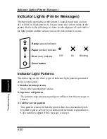
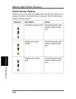
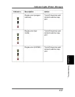
Page 211: ...curs Indicator Light Patterns The following are the three types of indicator light patterns produced on the control panel 1 Standard status pattern Shows the current printer status 2 Operator call pattern The printer stops processing and goes offline when this message is shown 3 Call for service pattern This pattern is shown when the printer detects a mechanical prob lem that requires service by a...

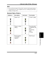
Page 212: ... s status by checking the informa tion that appears on your computer screen see Starting Up the Status Display on page 4 59 Indicators Description Indicators Description Power is off Printer is ready Power on initial setting Receiving data via parallel inter face Processing data Printing Receiving data via network interface Warming up ...

Page 213: ...6 32 Indicator Lights Printer Messages Chapter 6 Troubleshooting Slow blinking Power save Mode Indicators Description Indicators Description ...

Page 214: ... cover Memory overflow Press the panel button to perform a form feed Install an optional expansion memory SIMM into the printer or decrease the amount of data being sent to the printer Data is currently being compressed because more data is being pro cessed than can be managed by the amount of memory installed in your printer You may notice a difference in image quality when compressed data is pri...

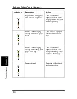
Page 215: ... feed tray and continue printing Printer is standing by waiting for manual paper feed Load a sheet of paper onto the manual feed tray Printer is standing by waiting for feeding from paper feed tray Load paper of the appropriate size onto the specified tray Tray 1 Tray 2 or Tray 3 Paper misfeed Clear the misfeed and continue printing Indicators Description Action ...

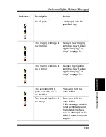
Page 216: ... 1 The imaging cartridge is out of toner Replace the imaging cartridge See Replac ing the Imaging Car tridge on page 5 1 The second or third paper cassette unit is not installed Press and hold the panel button The network interface is not ready Press and hold the panel button If this message persists for an extended period the network interface may be damaged or dis abled Contact customer support ...

Page 217: ... try turning the printer off and then back on again If the problem persists contact customer support Indicators Description Action Controller memory error Turn off the printer and contact customer sup port Engine error main motor Turn off the printer and contact customer sup port Engine error fusing unit Turn off the printer and contact customer sup port ...

Page 218: ...ssages Engine error polygon scanner Turn off the printer and contact customer sup port Engine error fan motor Turn off the printer and contact customer sup port Engine error HSYNC Turn off the printer and contact customer sup port Indicators Description Action ...

Page 219: ...6 38 Indicator Lights Printer Messages Chapter 6 Troubleshooting ...

Page 220: ...Chapter 7 Specifications 7 7Chapter Specifications ...

Page 221: ...Chapter 7 Specifications ...

Page 222: ...First print One sided Within 18 seconds A4 Let ter size print Double sided Within 29 seconds A4 Letter size print Warm up time 23 seconds or less when the printer is working with the standard 8 MB memory installed Paper sizes Standard size A4 A5 JIS B5 Letter Legal Executive Commercial 10 Monarch DL C5 and B5 envelopes Non standard size Widths 9 22 cm 3 1 2 in 8 1 2 in Lengths 15 35 5 cm 6 in to 1...

Page 223: ... fluctuation of 10 C 18 F per hour Operating humidity 15 to 85 with fluctuation of 20 per hour Imaging cartridge life 9 000 A4 Letter size prints black to white ratio of 5 or less The imaging cartridge that comes with the printer is capable of producing approximately 5 000 A4 Letter size prints Power supply 220 240 V at 50 60 Hz Power consumption Operating 820 W or less Standby average 60 W or les...

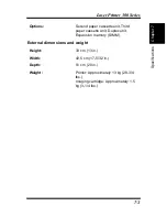
Page 224: ...nsions and weight Options Second paper cassette unit Third paper cassette unit Duplex unit Expansion memory SIMM Height 33 cm 13 in Width 43 5 cm 17 5 32 in Depth 51 cm 20 in Weight Printer Approximately 13 kg 28 3 4 lbs Imaging cartridge Approximately 1 5 kg 3 1 4 lbs ...

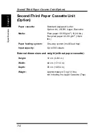
Page 225: ...er cassette Standard equipped Letter Option A4 JIS B5 Legal Executive Media Plain paper 60 90 g m2 16 24 lbs Recycled paper 60 90 g m2 16 24 lbs Paper feeding system One way system multi feed tray Input capacity Up to 500 sheets Height 12 cm 4 3 4 in Width 44 cm 17 1 4 in Depth 35 cm 13 3 4 in Weight Approximately 4 5 kg 10 lbs not including the Legal Cassette Tray ...

Page 226: ...r feeding system One way system Media Plain paper 60 90 g m2 16 24 lbs Recycled paper 60 90 g m2 16 24 lbs Paper feeding system One way system Operating temperature 10 35 C 50 95 F Operating humidity 15 to 85 Height 27 cm 10 3 4 in Width 32 cm 12 3 4 in Depth 15 cm 6 in Weight Approximately 2 3 kg 5 lbs ...

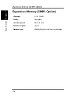
Page 227: ...sion Memory SIMM Option Chapter 7 Specifications Expansion Memory SIMM Option Capacity 8 16 32 MB Parity Non parity Access speed 60 ns or less Number of pins 72 pin Module type SIMM Single In line Memory Module ...

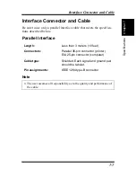
Page 228: ...ecifica tions described below Parallel Interface Note Length Less than 3 meters 10 feet Connectors Parallel 36 pin connector printer EIA 25 pin connector computer Cable type Shielded Each signal and ground pair should be twisted Pin assignments IEEE 1284 type B connector The user assumes all responsibility as to the quality and performance of the cable ...

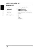
Page 229: ...Chapter 7 Specifications USB Interface Length Less than 15 feet 5 meters Connectors Series B plug printer Series A plug computer Cable type Require twisted data conductors or a shielded Pin assignments 1 VBUS 2 D 3 D 4 GND Shell Shield ...

Page 230: ...Appendix Glossary A Glossary Appendix A ...

Page 231: ...Glossary Appendix A ...

Page 232: ...mouse button quickly Often used to select an object SEE double click control panel A bank of indicators that show the current status of the printer Panel buttons that are located on the control panel make it possible to perform a variety of different operations default Settings that are preset in the absence of user specified settings dialog box A box that appears in order for the user to input in...

Page 233: ...outputted from the printer The tray can hold up to 250 sheets of paper 500 sheet second cassette option SEE Tray 2 500 sheet third cassette option SEE Tray 3 fusing unit A part of the printer that fixes the toner image onto the paper gray scale A series of shades ranging from black to white used to add detail to photo or scanned images etc halftone A printing technique using a pattern of dots to c...

Page 234: ...er Network Interface Card NIC Facilitates the network connection of the printer off line A state in which the printer cannot receive data or perform any other operation on line A state in which the printer can receive data and operate operating system A program or group of programs that control the functions of the computer and its peripheral devices such as the printer output tray SEE face down t...

Page 235: ...ached to the computer such as a printer PostScript Developed by Adobe Systems PostScript is one of the most well known page description languages PostScript fonts Precise high quality fonts that are engineered to be printed using a PostScript compatible computer power cord socket Connects the power cord and the printer power switch Turns power to the printer on and off printer A peripheral device ...

Page 236: ...open by pressing a release button Opening the cover provides easy access to the interior of the printer to perform basic maintenance procedures including the installation and replacement of the imaging cartridge as well as clearing paper misfeeds top cover release button This button releases the hinge that locks the cover of the printer SEE top cover Tray 1 A tray that can hold up to 250 sheets of...

Page 237: ...3 cassettes can be installed into the third paper cassette unit SEE third paper cassette unit Each cassette can hold up 500 sheets of one of the following paper sizes A4 JIS B5 Legal Letter and Executive watermark A superimposed line of text or graphic upon a printed document ...

Reviews: