


TAC-7X
MANUAL
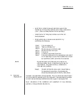
Step 4. Refer to Table 6-1. If the TAC Crimper has an
operator-adjustable "G" dimension control, set
the control to setting 6 (the largest wire gauge). If
the setting is not adjustable, perform the GO
/NO-GO tests and adjust to correspond to the
largest wire size.
TABLE 6-1. GO NO-GO DIMENSIONS
Step 5.
Using only hand pressure, extend the arbor as far
to the left as it will go.
Step 6. Using appropriate GO NO-GO gauges, open the
funnel and insert gauges into the indenters to
determine the "G" dimensions.
Conta
ct
Gaug
Setting
Wire Gauge
Go
No-Go
22
1
26
.016
.021
22
2
24
.019
.024
22
3
22
.022
.027
20
4
24
.025
.030
20
5
22
.029
.034
20
6
20
.033
.038
16
1 or 4
20
.029
.034
16
2 or s
18
.033
.038
16
3 or 6
16
.037
.042
Summary of Contents for TAC-7AE
Page 6: ...Figure 1 1 TAC 7X Front View ...
Page 8: ... Figure 1 2 Wire Insertion Through Funnel ...
Page 12: ...Figure2 1 Pneumatic Hook Up ...
Page 14: ... Fiqure 2 4 Track Drop Tube Escapement ESCAPEMENT SYSTEM _ _ _ BR ASSEMBL I TRA ...
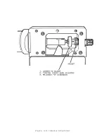
Page 18: ... ARBOR COVER PLA TE REMOVED Figure 3 1 Crimp Cylinder Arbor Open ...
Page 20: ... ARBOR COVER PLAT E REMOVED Figure 3 2 Crimp Cylinder Arbor Closed ...
Page 23: ... Crimp Inspection Points Improper Crimps ...
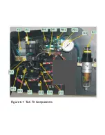
Page 33: ...Figure 6 1 TAC 7X Components ...
Page 34: ...Figure 6 2 Control Box Components Figure 6 2 TAC 7X Components Right View ...
Page 37: ...Figure 6 3 Contact Track Feed Air Adjustments ...
Page 42: ... Figure 6 4 Indenter Plate Removal ...
Page 43: ...HOSE CLAMP CAREFULL Y REMOVE Figure 6 5 Indenter Replacement ...
Page 47: ...Figure 6 6 Indenter Adjustment ...
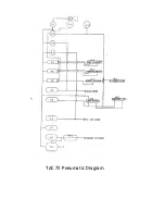
Page 52: ...TAC 7X Pneumatic Diagram ...


