TAC-7X
MANUAL
Step 5.
Step 6.
Step 7.
Step 8.
Step 9.
Step 10.
Step 11.
Step 12.
Step 13.
Turn on air supply.
Plug exhaust port of vacuum generator (VG-1) with
finger for approximately 10 seconds.
Repeat step 6 several times.
Turn off air supply.
Replace transfer tip to tip holder.
Replace control unit cover plate.
Plug power cord to wall outlet.
Turn on air supply.
Test part detection sensor as detailed in
Section 2, Par.2-6.
Air supply cleanliness for the TAC is most important. A clean, dry air
source in conjunction with periodic filter inspection will prevent pneu-
matic components from jamming, clogging or otherwise malfunctioning.
6-3 Contact Track
Feed
The feed of contacts onto and into the track assembly is the result of
the feeder-bowl vibrations and the setting of several air pressure
controls. The TAC base plate must be level and solid.
Refer to Figure 6-3. Feeder-bowl vibrations transport contacts to the top
of the bowl where the combination of vibrations and air pressure from
the tube (controlled by BR-1) permits contacts to orient themselves
vertically in the track. Air pressure controlled by (BR-2) forces the
contacts towards the escapement system. Air pressure controlled by
(BR-3) forces contacts not oriented vertically to return to the feeder
bowl. The air pressure controls are factory set. The air tube location is
factory set and should not be changed. The three air pressure controls
(refer to Figure 6-2) may be adjusted in the field.
In general, if contacts are not orienting themselves properly in the feed
track, adjusting the feeder-bowl vibration amplitude (located on the
cabinet front panel) and varying BR-1,will correct the feed. If contacts
are not aligning themselves tightly against one another and against the
escapement system, adjust BR-2 and/or BR-3. Care must be taken to
avoid setting any pressure so high that contacts are "bouncing" and not
setting against the escapement system firmly.
Summary of Contents for TAC-7AE
Page 6: ...Figure 1 1 TAC 7X Front View ...
Page 8: ... Figure 1 2 Wire Insertion Through Funnel ...
Page 12: ...Figure2 1 Pneumatic Hook Up ...
Page 14: ... Fiqure 2 4 Track Drop Tube Escapement ESCAPEMENT SYSTEM _ _ _ BR ASSEMBL I TRA ...
Page 18: ... ARBOR COVER PLA TE REMOVED Figure 3 1 Crimp Cylinder Arbor Open ...
Page 20: ... ARBOR COVER PLAT E REMOVED Figure 3 2 Crimp Cylinder Arbor Closed ...
Page 23: ... Crimp Inspection Points Improper Crimps ...
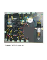
Page 33: ...Figure 6 1 TAC 7X Components ...
Page 34: ...Figure 6 2 Control Box Components Figure 6 2 TAC 7X Components Right View ...
Page 37: ...Figure 6 3 Contact Track Feed Air Adjustments ...
Page 42: ... Figure 6 4 Indenter Plate Removal ...
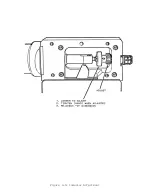
Page 43: ...HOSE CLAMP CAREFULL Y REMOVE Figure 6 5 Indenter Replacement ...
Page 47: ...Figure 6 6 Indenter Adjustment ...
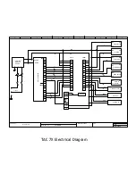
Page 52: ...TAC 7X Pneumatic Diagram ...


