TAC-7X
MANUAL
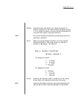
Step 4.
Carefully raise the TAC using only the baseplate for lifting,
then set the machine on a smooth level working surface
CAUTION!!
3.
Pneumatic
Hook-Up
NOTE
NOTE
Remember........the TAC weighs about 70 pounds, make sure appropriate
lifting devices are used.
Step 6.
The shipping container may be discarded. However, if
reshipment to another location is possible, it is recommended
that the container, fasteners and packing mate rial be
retained.
INITIAL INSTALLATION AND SETUP
Perform the following steps to hook-up the pneumatic input:
Step 1. Referring to Figure 2-1. obtain a 1/4-in. male air fitting (not
supplied with the TAC) that is compatible with the air supply and
sleeve valve on top of the controller cabinet.
The sleeve valve is used to turn the air and controller ON and OFF. The air
supply must be approx. 80 minimum - 125 maximum through a 3/8- in.
hose or conduit. Air must be clean, dry and oil-free.
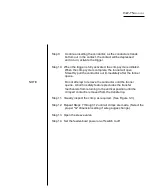
Step 2.
Install the air fitting.
Step 3.
Connect the air supply to the sleeve valve. DO
DO NOT CLOSE THE SLEEVE VALVE AT THIS TIME
Summary of Contents for TAC-7AE
Page 6: ...Figure 1 1 TAC 7X Front View ...
Page 8: ... Figure 1 2 Wire Insertion Through Funnel ...
Page 12: ...Figure2 1 Pneumatic Hook Up ...
Page 14: ... Fiqure 2 4 Track Drop Tube Escapement ESCAPEMENT SYSTEM _ _ _ BR ASSEMBL I TRA ...
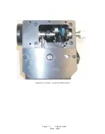
Page 18: ... ARBOR COVER PLA TE REMOVED Figure 3 1 Crimp Cylinder Arbor Open ...
Page 20: ... ARBOR COVER PLAT E REMOVED Figure 3 2 Crimp Cylinder Arbor Closed ...
Page 23: ... Crimp Inspection Points Improper Crimps ...
Page 33: ...Figure 6 1 TAC 7X Components ...
Page 34: ...Figure 6 2 Control Box Components Figure 6 2 TAC 7X Components Right View ...
Page 37: ...Figure 6 3 Contact Track Feed Air Adjustments ...
Page 42: ... Figure 6 4 Indenter Plate Removal ...
Page 43: ...HOSE CLAMP CAREFULL Y REMOVE Figure 6 5 Indenter Replacement ...
Page 47: ...Figure 6 6 Indenter Adjustment ...
Page 52: ...TAC 7X Pneumatic Diagram ...


