


TAC
·
7AE
MANUAL
NOTE
NOTE
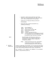
Be sure to use gauges corresponding to proper wire
gauge and contact gauge.
Step 7.
If the "G" dimension is acceptable, go to Step
14. If the "G" dimension is not acceptable, go to
Step 8.
Step 8.
Refer to Figure 6-6.
Step 9.
Loosen the Stafford clamp collar.
Step 10. Rotate the "ADJUST' adjustable stop counter
clockwise to decrease the "G" dimension, or
clockwise to increase the "G" dimension.
Step 11. Repeat Steps 5 through 10 until the "G" dimension is
within acceptable parameters.
Step 12. Hand-tighten the Stafford clamp collar, being
careful not to change the adjustable stop posi-
tion.
Step 13. Repeat steps 5 and 6.
Operator-adjustable "G" dimension TAC's should be
adjusted at setting 6. If desired after adjustment has been
completed, GO NO-GO verification may be performed for
the remaining settings.
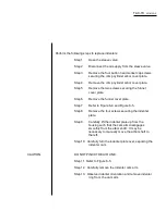
Step 14. Install the crimp cylinder arbor cover plate and the
funnel cover plate removed in Step 3.
Step 15. Connect the air supply to the sleeve valve.
Step 16. Set the feeder-bowl power on-off switch to on.
Step 17. Close the sleeve valve.
Summary of Contents for TAC-7AE
Page 6: ...Figure 1 1 TAC 7X Front View ...
Page 8: ... Figure 1 2 Wire Insertion Through Funnel ...
Page 12: ...Figure2 1 Pneumatic Hook Up ...
Page 14: ... Fiqure 2 4 Track Drop Tube Escapement ESCAPEMENT SYSTEM _ _ _ BR ASSEMBL I TRA ...
Page 18: ... ARBOR COVER PLA TE REMOVED Figure 3 1 Crimp Cylinder Arbor Open ...
Page 20: ... ARBOR COVER PLAT E REMOVED Figure 3 2 Crimp Cylinder Arbor Closed ...
Page 23: ... Crimp Inspection Points Improper Crimps ...
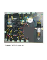
Page 33: ...Figure 6 1 TAC 7X Components ...
Page 34: ...Figure 6 2 Control Box Components Figure 6 2 TAC 7X Components Right View ...
Page 37: ...Figure 6 3 Contact Track Feed Air Adjustments ...
Page 42: ... Figure 6 4 Indenter Plate Removal ...
Page 43: ...HOSE CLAMP CAREFULL Y REMOVE Figure 6 5 Indenter Replacement ...
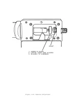
Page 47: ...Figure 6 6 Indenter Adjustment ...
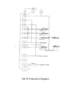
Page 52: ...TAC 7X Pneumatic Diagram ...


