


TAC-7X
MANUAL
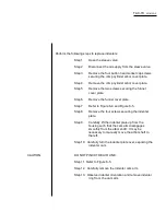
Step 18. Verify a contact is seated in the transfer tip and
that the transfer tip is in the ready-to-crimp
position.
Step 19. Using a conductor of proper material and gauge,
strip it to the proper strip length. Be sure the "G"
dimension, if applicable, is at the proper setting.
Step 20. While being careful that all conductor strands enter
the funnel without bending back, insert the
conductor into the funnel until it bottoms out.
Step 21. Crimp the conductor.
Step 22.
Inspect the crimp per required specifications.
Step 23. Repeat Steps 19 through 22 for each conductor
wire gauge to obtain the necessary specimens;
inspect per established procedure.
Step 24. After all specimens have been produced, set the
power on-off switch to off and open the sleeve
valve.
Step 25. If crimps meet all established parameters, certify
the TAC-7X for production use, and establish a
periodic verification schedule.
Summary of Contents for TAC-7AE
Page 6: ...Figure 1 1 TAC 7X Front View ...
Page 8: ... Figure 1 2 Wire Insertion Through Funnel ...
Page 12: ...Figure2 1 Pneumatic Hook Up ...
Page 14: ... Fiqure 2 4 Track Drop Tube Escapement ESCAPEMENT SYSTEM _ _ _ BR ASSEMBL I TRA ...
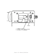
Page 18: ... ARBOR COVER PLA TE REMOVED Figure 3 1 Crimp Cylinder Arbor Open ...
Page 20: ... ARBOR COVER PLAT E REMOVED Figure 3 2 Crimp Cylinder Arbor Closed ...
Page 23: ... Crimp Inspection Points Improper Crimps ...
Page 33: ...Figure 6 1 TAC 7X Components ...
Page 34: ...Figure 6 2 Control Box Components Figure 6 2 TAC 7X Components Right View ...
Page 37: ...Figure 6 3 Contact Track Feed Air Adjustments ...
Page 42: ... Figure 6 4 Indenter Plate Removal ...
Page 43: ...HOSE CLAMP CAREFULL Y REMOVE Figure 6 5 Indenter Replacement ...
Page 47: ...Figure 6 6 Indenter Adjustment ...
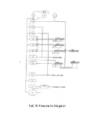
Page 52: ...TAC 7X Pneumatic Diagram ...


