Operating Procedures
Section 4
TAC-7X
MANUAL
1. Introduction
2. Normal
Operation
The TAC series crimpers are simple to operate. No previous experience
with crimpers of any kind is required; however, operators need to exercise
reasonable care when operating the TAC and should be familiar with
acceptable crimp criteria. No adjustments to the equipment should be
made unless specific procedures in this manual are followed, and then only
when authorized.
This section assumes the TAC has been set-up properly and that Crimp
Verification has been performed (Sections 2 and 3).
Read this section completely before operating the TAC.
Perform the following steps to operate the TAC:
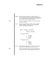
Step 1. Set the feeder bowl power on-off switch to on.
CAUTION
KEEP HANDS CLEAR OF THE TRANSFER MECHANISM
DURING OPERATION AND WHEN CLOSING THE SLEEVE
VALVE.
NOTE
IMPORTANT: NEVER TURN ON SLEEVE VALVE WITH A
CONTACT LOADED INTHE TRANSFER TIP.IF LOADED, TURN
OFF SLEEVE VALVE, CLEAR THE TIP AND PRO CEED TO STEP
2.
Step 2.
Close the sleeve valve.
Step 3.
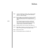
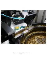
Observe that the feeder-bowl is vibrating and transporting
contacts to the top of the bowl.
·
Step 4.
Observe that contacts are entering the track assembly and are
orienting themselves vertically.
Step 5.
Depress the First Part Switch.
Summary of Contents for TAC-7AE
Page 6: ...Figure 1 1 TAC 7X Front View ...
Page 8: ... Figure 1 2 Wire Insertion Through Funnel ...
Page 12: ...Figure2 1 Pneumatic Hook Up ...
Page 14: ... Fiqure 2 4 Track Drop Tube Escapement ESCAPEMENT SYSTEM _ _ _ BR ASSEMBL I TRA ...
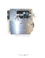
Page 18: ... ARBOR COVER PLA TE REMOVED Figure 3 1 Crimp Cylinder Arbor Open ...
Page 20: ... ARBOR COVER PLAT E REMOVED Figure 3 2 Crimp Cylinder Arbor Closed ...
Page 23: ... Crimp Inspection Points Improper Crimps ...
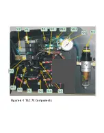
Page 33: ...Figure 6 1 TAC 7X Components ...
Page 34: ...Figure 6 2 Control Box Components Figure 6 2 TAC 7X Components Right View ...
Page 37: ...Figure 6 3 Contact Track Feed Air Adjustments ...
Page 42: ... Figure 6 4 Indenter Plate Removal ...
Page 43: ...HOSE CLAMP CAREFULL Y REMOVE Figure 6 5 Indenter Replacement ...
Page 47: ...Figure 6 6 Indenter Adjustment ...
Page 52: ...TAC 7X Pneumatic Diagram ...


