


TAC-7X
MANUAL
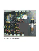
The system air supply is filtered at (F-1) and overall system air pressure is
regulated by Regulator (R-1). (FOR LOCATION OF COMPONENTS,
REFER TO FIGURES 6-1 & 6-2, in the Maintenance section). The air
pressure at R-1 should be approximately 85 PSIG, and may be
monitored with Pressure Gauge (G-1). Pressure to maintain the slide
cylinder (SC-1) in the up (ready-to-crimp) position is regulated by Regulator
(R-2). This pressure should be approximately 20 PSIG, and may be
monitored with Pressure Gauge (G-1) by depressing PB-1 switch.
Regulators(R-3 and R-4) are factory-adjusted to approximately 4 to 8 PSIG
to provide low pressure pilot signals for the slide and crimp complete
sensors. No adjustments should be made unless absolutely certain the
adjustment is required. Indiscriminate changes to regulator or switch
settings should not be made. A clean air supply is imperative to proper
system operation. Filter F-1 should be drained or changed, as required.
3.
Initial Turn-On/
Reset
Reset occurs any time the operator-controlled sleeve valve is initially
closed, or opened and then closed.
Upon closing the sleeve valve, air pressure is supplied to the TAC.
When the sleeve value is closed, the TAC cycles to insure that all cylinders
are in the proper position:
-Crimp Cylinder is retracted: V-1 OFF
-Transfer Arm is extended (forward): V-2 OFF
-Escapement Cylinder is Retracted
-Slide Cylinder is extended: V-3 OFF
-Wire Funnel Cylinders are retracted: V-3 OFF
No contact will be fed to the Transfer Tip. Depressing the First Part (FP- 1A)
pushbutton switch momentarily while the feeder-bowl is on and properly set,
will advance the system to place a contact in the Transfer Tip.
.
(S-3) is switched on when the First Part Pushbutton is depressed.
Summary of Contents for TAC-7AE
Page 6: ...Figure 1 1 TAC 7X Front View ...
Page 8: ... Figure 1 2 Wire Insertion Through Funnel ...
Page 12: ...Figure2 1 Pneumatic Hook Up ...
Page 14: ... Fiqure 2 4 Track Drop Tube Escapement ESCAPEMENT SYSTEM _ _ _ BR ASSEMBL I TRA ...
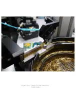
Page 18: ... ARBOR COVER PLA TE REMOVED Figure 3 1 Crimp Cylinder Arbor Open ...
Page 20: ... ARBOR COVER PLAT E REMOVED Figure 3 2 Crimp Cylinder Arbor Closed ...
Page 23: ... Crimp Inspection Points Improper Crimps ...
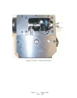
Page 33: ...Figure 6 1 TAC 7X Components ...
Page 34: ...Figure 6 2 Control Box Components Figure 6 2 TAC 7X Components Right View ...
Page 37: ...Figure 6 3 Contact Track Feed Air Adjustments ...
Page 42: ... Figure 6 4 Indenter Plate Removal ...
Page 43: ...HOSE CLAMP CAREFULL Y REMOVE Figure 6 5 Indenter Replacement ...
Page 47: ...Figure 6 6 Indenter Adjustment ...
Page 52: ...TAC 7X Pneumatic Diagram ...


