Initial Set-Up
Section 2
TAC-7X
MANUAL
1. Introduction
CAUTION
Although all TAC's are ruggedly constructed, adequate precautions
must be observed and all instructions followed to prevent damage to
the device during the Initial Set-up.
Read this entire section before proceeding. The time required to have
this TAC ready for CrimpVerification {Section 3) is less than one hour.
2. Uncrating/
Unpacking
NOTE
The shipping container in which the TAC is transported is a three piece
design constructed to ensure safe arrival of the device.
The bottom base piece of the container holds the TAC; the other
pieces of the shipping container consists of the top and four sides,
which are secured to the bottom base by mounting straps.
To Uncrate/Unpack the TAC:
Step 1.
Carefully cut all mounting straps surrounding the ship
ping container.
Step 2.
Carefully lift the top and sides of the container until all
sides are clear of the TAC.
Step 3.
Inspect for damage.
If damage due to shipping is observed, do not continue. Contact
the factory and the shipping carrier.
Lift and transport the TAC using only the baseplate Do not lift, pull
shove or jostle the feeder bowl, the crimp cylinder or any component
mounted on the baseplate.
Damage
will
result!!
Summary of Contents for TAC-7AE
Page 6: ...Figure 1 1 TAC 7X Front View ...
Page 8: ... Figure 1 2 Wire Insertion Through Funnel ...
Page 12: ...Figure2 1 Pneumatic Hook Up ...
Page 14: ... Fiqure 2 4 Track Drop Tube Escapement ESCAPEMENT SYSTEM _ _ _ BR ASSEMBL I TRA ...
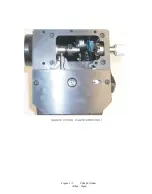
Page 18: ... ARBOR COVER PLA TE REMOVED Figure 3 1 Crimp Cylinder Arbor Open ...
Page 20: ... ARBOR COVER PLAT E REMOVED Figure 3 2 Crimp Cylinder Arbor Closed ...
Page 23: ... Crimp Inspection Points Improper Crimps ...
Page 33: ...Figure 6 1 TAC 7X Components ...
Page 34: ...Figure 6 2 Control Box Components Figure 6 2 TAC 7X Components Right View ...
Page 37: ...Figure 6 3 Contact Track Feed Air Adjustments ...
Page 42: ... Figure 6 4 Indenter Plate Removal ...
Page 43: ...HOSE CLAMP CAREFULL Y REMOVE Figure 6 5 Indenter Replacement ...
Page 47: ...Figure 6 6 Indenter Adjustment ...
Page 52: ...TAC 7X Pneumatic Diagram ...


