


TAC-7X
MANUAL
NOTE
NOTE
In proper operating order, the Transfer Arm will never
retract with a contact present in the Transfer Tip.
This feature prevents the possibility of dropping a
contact into a already loaded transfer tip.
When the Transfer Arm reaches the vertical position, a limit switch (LS-
1) is engaged and the following events occur:
-Limit Switch sensor (S-2) is turned on
-High pressure is supplied to Slide Cylinder, allowing it to stay
in the full extended position.
-V-3 is deactivated closing funnels
-Escapement Cylinder (EC-1) is activated, allowing a
contact to be advanced from the track assembly to the
drop tube.
If the contact exits the Drop Tube and seats properly in the Transfer Tip,
adequate vacuum will exist to switch on the Transfer Tip Sensor, (S-6).
Supply for Vacuum Sensor switch is provided by Vacuum Generator
(VG-1).
If a contact does not seat properly in the Transfer Tip, the
cycle will terminate until reset.
With S-6 turned on again, V-2 is turned off, allowing the Transfer Arm to
return to the "ready to crimp" position.
The TAC is now ready to have another properly stripped conductor inserted
in the wire funnel and commence another crimping cycle.
Summary of Contents for TAC-7AE
Page 6: ...Figure 1 1 TAC 7X Front View ...
Page 8: ... Figure 1 2 Wire Insertion Through Funnel ...
Page 12: ...Figure2 1 Pneumatic Hook Up ...
Page 14: ... Fiqure 2 4 Track Drop Tube Escapement ESCAPEMENT SYSTEM _ _ _ BR ASSEMBL I TRA ...
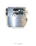
Page 18: ... ARBOR COVER PLA TE REMOVED Figure 3 1 Crimp Cylinder Arbor Open ...
Page 20: ... ARBOR COVER PLAT E REMOVED Figure 3 2 Crimp Cylinder Arbor Closed ...
Page 23: ... Crimp Inspection Points Improper Crimps ...
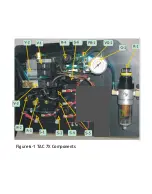
Page 33: ...Figure 6 1 TAC 7X Components ...
Page 34: ...Figure 6 2 Control Box Components Figure 6 2 TAC 7X Components Right View ...
Page 37: ...Figure 6 3 Contact Track Feed Air Adjustments ...
Page 42: ... Figure 6 4 Indenter Plate Removal ...
Page 43: ...HOSE CLAMP CAREFULL Y REMOVE Figure 6 5 Indenter Replacement ...
Page 47: ...Figure 6 6 Indenter Adjustment ...
Page 52: ...TAC 7X Pneumatic Diagram ...


