TAC-7X
MANUAL
Parts
Section 7
7-1
Reference
Li st
Designation
S-1
N-1 Slide Sensor Switch
TAC-F-4200-15
S-2
Limit Sensor Switch
TAC-F-4200-60
S-3
First Part Sensor Switch
TAC-F-4200-60
S-4
G-stop Sensor Switch
TAC-F-4200-15
S-5
Air ON/OFF Sensor Switch
TACF-4200-60
S-6
Transfer Tip Sensor S'Nitch
TAC-F-4200-X30
V-1
Crimp Cylinder Valve
TAC-A-110-4EI
V-2
Transfer Arm Valve
TAC-A-110-4EI
V-3
Funnel Cylinder/N-1 Slide
TAC-A-110-4EI
Cylinder Valve
R-1
System Air Regulator
TAC-601-3009-2
R-2
N-1.Slide Cylinder Regulator
TAC-R-900-30
R-3
N-1 Slide Sensor Regulator
TAC-R-900-10
R-4
G-stop Sensor Regulator
TAC-R-900-10
VG-1
Vacuum Generator
TAC-ME-03
G-1
Gauge (R-1)
TAC-206804
G-2
Gauge (R-2)
TAC-206804
FP-1
First Part Switch
TAC-SV-3-M5
LS-1
Limtt Switch
TAC-41P
FC-1
Funnel Cylinder (2)
TAC-SM3-2
SC-1
N-1 Slide Cylinder
TAC-SM3-2
EC-1
Escapement Cylinder
TAC-8-BFD-1
CR-1
Crimp Cylinder
TAC-083-527
TA-1
RFV-1
Transfer Arm Cylinder
Vacuum Filter
TAC-6DP-3
..
TAC-4LF010000
Description
Part Number
Summary of Contents for TAC-7AE
Page 6: ...Figure 1 1 TAC 7X Front View ...
Page 8: ... Figure 1 2 Wire Insertion Through Funnel ...
Page 12: ...Figure2 1 Pneumatic Hook Up ...
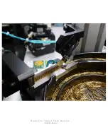
Page 14: ... Fiqure 2 4 Track Drop Tube Escapement ESCAPEMENT SYSTEM _ _ _ BR ASSEMBL I TRA ...
Page 18: ... ARBOR COVER PLA TE REMOVED Figure 3 1 Crimp Cylinder Arbor Open ...
Page 20: ... ARBOR COVER PLAT E REMOVED Figure 3 2 Crimp Cylinder Arbor Closed ...
Page 23: ... Crimp Inspection Points Improper Crimps ...
Page 33: ...Figure 6 1 TAC 7X Components ...
Page 34: ...Figure 6 2 Control Box Components Figure 6 2 TAC 7X Components Right View ...
Page 37: ...Figure 6 3 Contact Track Feed Air Adjustments ...
Page 42: ... Figure 6 4 Indenter Plate Removal ...
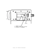
Page 43: ...HOSE CLAMP CAREFULL Y REMOVE Figure 6 5 Indenter Replacement ...
Page 47: ...Figure 6 6 Indenter Adjustment ...
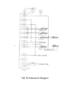
Page 52: ...TAC 7X Pneumatic Diagram ...

