


EO2P User Guide |Page 53
33706 Rev. A
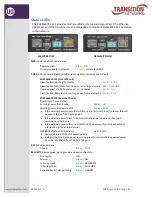
RJ45 Cable Configurations
Install a
straight-through
RJ45 connectorized cable between Local unit
DATA + PWR OUT
and the Remote unit
DATA + PWR IN
RJ45 connectors.
The cable can be fully pinned or can use various pin combinations of each connector.
Supported RJ-45 cable configurations are described below.
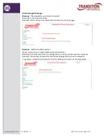
One Pair (2-Wire) RJ45
Connect pins 4 & 5 of each connector.
Two Pair (4-Wire) RJ45
Connect pins 4 & 5 and one other pair using your choice of pins 3 & 6, or pins 1 & 2, or
pins 7 & 8 of each connector.
Three Pair (6-Wire) RJ45
Connect pins 4 & 5 and two other pairs using your choice of pins 3 & 6, or pins 1 & 2, or
pins 7 & 8 of each connector.
Four Pair (8-Wire) RJ45
Connect pins 4 & 5 and three other pairs using pins 3 & 6, pins 1 & 2, and pins 7 & 8 of
each connector.
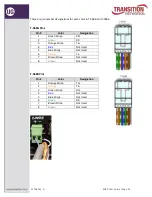
RJ45 Pin Number Designations
RJ45 cables have eight color-coded wires, and the plugs have eight pins and conductors.
Eight wires are used as 4 pairs, each representing positive and negative polarity.
The most common 100-Base-T wiring standards are EIA 568A and 568B standards.
An RJ-45 data cable contains 4 pairs of wires; each pair consists of a solid colored wire
and a stripe of the same color. The two wiring standards for RJ-45 wiring are T-568A and
T-568B. Although there are 4 pairs of wires, 10BaseT/100BaseT Ethernet uses only
2 pairs:
Orange
and
Green
. The two wiring standards are used to create a cross-over
cable (T-568A on one end and T-568B on the other end), or a straight-through cable
(T-568B or T-568A on both ends).
The RJ45 cable may be straight-through or cross-over. To create a straight-through cable,
either use T-568A on both ends of the cable or use T-568B on both ends of the cable.
If using cross-over cable, all pairs must be crossed.


