2-42
CHAPTER 2 FINISHER UNIT BASIC OPERATION
I.
Shutter Operation
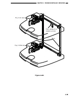
When the tray-1 passes the delivery slot, the finisher controller PCB closes the shutter mounted
on the delivery slot before moving the tray, preventing the existing stack on the tray by the delivery
slot and intrusion of the hands.
The shutter moves up (to close) when the second feed motor (M8) rotates counterclockwise,
and is held in position when the motor stops. When the second feed motor rotates counterclockwise
once again, it moves down (to open) to enable delivery.
When the shutter is held at the up position, claws slide out of the swing guide to engage the
back of the shutter. This way, the existing slack and the swing guide engage while the tray is moved,
preventing the guide from opening. The claws slide in when the shutter is moved down to release
the engagement.
The upward movement of the shutter is monitored by the shutter closed detecting switch (MS4),
and the downward movement is monitored by the shutter open sensor (PI5).
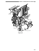
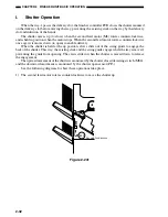
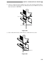
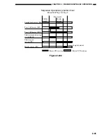
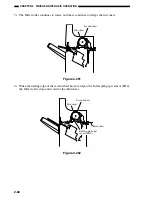
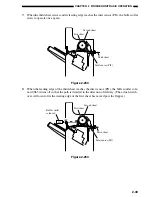
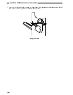
See the following diagrams for how these operations take place.
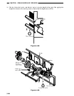
1) The second feed motor rotates counterclockwise to move the shutter up.
M8
Second feed motor
Figure 2-241
Summary of Contents for MJ-1027
Page 1: ...SERVICE MANUAL FINISHER MJ 1027 1028 File No SME040041A0 R04102169300 TTEC Ver01_2007 09 ...
Page 5: ...ii ...
Page 9: ...vi ...
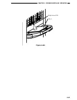
Page 70: ...2 41 CHAPTER 2 FINISHER UNIT BASIC OPERATION Height sensor PS1 Paper Figure 2 240 ...
Page 101: ...3 15 CHAPTER 3 SADDLE STITCHER UNIT BASIC OPERATION Figure 3 301 ...
Page 104: ...3 18 CHAPTER 3 SADDLE STITCHER UNIT BASIC OPERATION 2 A3 LD Paper Path 3 sheets Figure 3 303 ...
Page 116: ...3 30 CHAPTER 3 SADDLE STITCHER UNIT BASIC OPERATION Cam Mount Figure 3 404 ...
Page 173: ...6 CHAPTER 6 TROUBLESHOOTING II ARRANGEMENT OF ELECTRICAL PARTS A Finisher Unit ...
Page 235: ...2 17 2 HIGASHIGOTANDA SHINAGAWA KU TOKYO 141 8664 JAPAN ...

