i
This Service Manual contains basic data and figures for the Finisher (MJ-1027)/Saddle
Stitch Finisher (MJ-1028) needed to service the machine in the field.
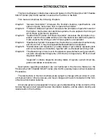
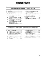
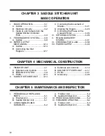
This manual comprises the following chapters:
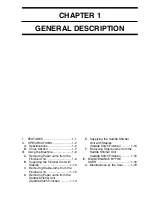
Chapter 1
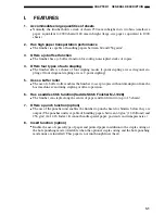
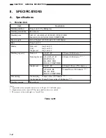
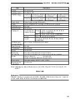
“General Description” introduces the finisher’s features, specifications, and
names of parts, and shows how to operate the finisher.
Chapter 2
“Finisher Unit Basic Operation” discusses the principles of operation used for
the finisher mechanical and electrical systems. It also explains the timing at
which these systems are operated.
Chapter 3
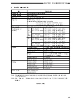
“Saddle Stitch Finisher Unit Basic Operation” discusses the principles of op-
eration used for the saddle stitcher unit’s mechanical and electrical systems.
It also explains the timing at which these systems are operated.
Chapter 4
“Mechanical System” discusses how the finisher is constructed mechanically,
and shows how it may be disassembled/assembled and adjusted.
Chapter 5
“Maintenance and Inspection” provides tables of periodically replaced parts
and consumables and durables, together with a scheduled servicing chart.
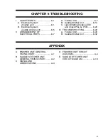
Chapter 6
“Troubleshooting” shows how to troubleshoot possible faults and gives electri-
cal parts arrangement diagrams, LED/check pin diagrams by PCB, and self
diagnosis tables.
“Appendix” contains diagrams showing tables of signals, overall circuit dia-
grams and tables of solvents/oils.
Descriptions regarding installation are not mentioned in this Service Manual as the
Finisher (MJ-1027)/Saddle Stitich Finisher (MJ-1028)’s packing boxes contain Installation
Procedures.
The descriptions in this Service Manual are subject to change without notice for prod-
uct improvement or other purposes, and major changes will be communicated in the form
of Service Information bulletins.
All service persons are expected to have a good understanding of the contents of this
Service Manual and all relevant Service Information bulletins, and be able to identify and
isolate faults in the machine.
INTRODUCTION
Summary of Contents for MJ-1027
Page 1: ...SERVICE MANUAL FINISHER MJ 1027 1028 File No SME040041A0 R04102169300 TTEC Ver01_2007 09 ...
Page 5: ...ii ...
Page 9: ...vi ...
Page 70: ...2 41 CHAPTER 2 FINISHER UNIT BASIC OPERATION Height sensor PS1 Paper Figure 2 240 ...
Page 101: ...3 15 CHAPTER 3 SADDLE STITCHER UNIT BASIC OPERATION Figure 3 301 ...
Page 104: ...3 18 CHAPTER 3 SADDLE STITCHER UNIT BASIC OPERATION 2 A3 LD Paper Path 3 sheets Figure 3 303 ...
Page 116: ...3 30 CHAPTER 3 SADDLE STITCHER UNIT BASIC OPERATION Cam Mount Figure 3 404 ...
Page 173: ...6 CHAPTER 6 TROUBLESHOOTING II ARRANGEMENT OF ELECTRICAL PARTS A Finisher Unit ...
Page 235: ...2 17 2 HIGASHIGOTANDA SHINAGAWA KU TOKYO 141 8664 JAPAN ...

