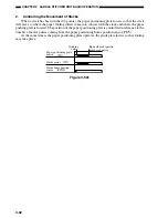
3-33
CHAPTER 3 SADDLE STITCHER UNIT BASIC OPERATION
3.
Folding a Stack
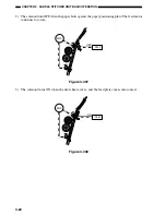
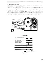
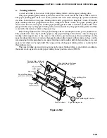
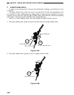
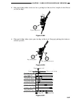
A stack is folded by the action of the paper folding rollers and the paper pushing plate.
The paper pushing plate pushes against the center of a stack toward the roller contact section.
The paper pushing plate starts at its home position and waits at the leading edge position until the
stack has been drawn to the paper folding roller and is gripped for a length of 10 mm. When the
paper folding roller has gripped the stack for a length of about 10 mm, the paper pushing plate
motor starts to rotate once again, and the paper pushing plate returns to its home position. The stack
gripped in this way by the paper folding roller is drawn further by the paper folding roller and then
is moved by the delivery roller to the paper tray.
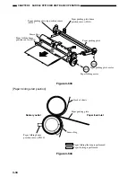
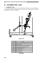
Half of the peripheral area of the paper folding rollers excluding the center part is punched out.
This punched out area only feeds the paper as the paper feeding roller (lower) contacts the paper
feeding roller (upper) only at the center of the roller to prevent the paper from wrinkling. As the
paper feeding roller (lower) contacts the paper feeding roller (upper) at their entire surfaces on the
remaining half of the peripheral area, paper folding starts from this half of the peripheral area, and
paper is fed while it is being folded. The stop position of the paper folding rollers is in this half of
the peripheral area.
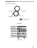
The paper folding start and stop positions on the paper folding rollers is controlled according to
the motor clock signals from the paper folding home position sensor (PI21S).
Paper folding
roller (lower)
Paper folding
roller (upper)
Sensor flag
Paper folding home
position sensor
(PI21S)
Paper pushing plate top
position sensor
(PI15S)
Paper pushing plate home
position sensor
(PI14S)
Paper pushing plate
Paper pushing plate motor
Paper folding motor
M2S
M8S
Stack of sheets
Figure 3-502
Summary of Contents for MJ-1027
Page 1: ...SERVICE MANUAL FINISHER MJ 1027 1028 File No SME040041A0 R04102169300 TTEC Ver01_2007 09 ...
Page 5: ...ii ...
Page 9: ...vi ...
Page 70: ...2 41 CHAPTER 2 FINISHER UNIT BASIC OPERATION Height sensor PS1 Paper Figure 2 240 ...
Page 101: ...3 15 CHAPTER 3 SADDLE STITCHER UNIT BASIC OPERATION Figure 3 301 ...
Page 104: ...3 18 CHAPTER 3 SADDLE STITCHER UNIT BASIC OPERATION 2 A3 LD Paper Path 3 sheets Figure 3 303 ...
Page 116: ...3 30 CHAPTER 3 SADDLE STITCHER UNIT BASIC OPERATION Cam Mount Figure 3 404 ...
Page 173: ...6 CHAPTER 6 TROUBLESHOOTING II ARRANGEMENT OF ELECTRICAL PARTS A Finisher Unit ...
Page 235: ...2 17 2 HIGASHIGOTANDA SHINAGAWA KU TOKYO 141 8664 JAPAN ...


