6-5
CHAPTER 6 TROUBLESHOOTING
07/09
B. Electrical System (saddle
stitcher unit)
1. Adjusting the Folding Position
The folding position is adjusted by
changing the settings of bits 6 through 8
of DIPSW1 on the saddle stitcher control-
ler PCB to match the stitching position (i.e.,
adjusting the distance over which the paper
positioning plate is moved to the folding po-
sition from the stitching position.)
If you have replaced the saddle stitcher
controller PCB, be sure to set the new DIP-
SW1 so that the settings will be the same as
those on the old DIPSW1. If, for any reason,
you must change the following position, per-
form the following steps:
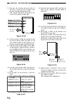
1) Turn the host machine OFF.
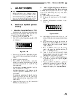
2) Remove the PCB cover, and set bits
1 through 4 of DIPSW1 on the saddle
stitcher controller PCB as indicated.
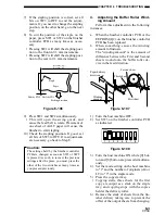
ON
1
2
3
4
5
6
7
8
Do not change bits 5 through 8.
Figure 6-113
3) Turn the host machine ON while [0] but-
ton and [8] button are pressed simultane-
ously.
4) Remove the rear cover of the saddle
stitcher unit, and tape the actuator of the
inlet cover sensor (PI9S) and the inlet
door switch (MS1S) of the saddle stitcher
unit in place.
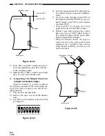
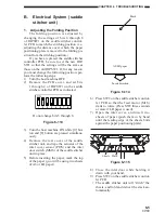
5) Before inserting the paper, mark the top
of the paper (you will be using two sheets
of A3 or LD paper).
Mark
A3/LD paper
Insert direction
Figure 6-114
6) Press SW2 on the saddle stitcher control-
ler PCB so that the feed motor (M1S)
starts to rotate. (Press SW2 three seconds
or more if LD paper is used).
7) Open the inlet cover, and insert two
sheets of paper (push them in by hand
until the leading edge of the sheets butts
against the paper positioning plate).
Sheets Mark
Figure 6-115
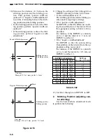
8) Close the inlet door while holding it
down with your hand.
9) Press SW2 on the saddle stitcher control-
ler PCB.
• The saddle stitcher unit will “stitch” the
sheets, and fold and deliver the stack au-
tomatically.
Summary of Contents for MJ-1027
Page 1: ...SERVICE MANUAL FINISHER MJ 1027 1028 File No SME040041A0 R04102169300 TTEC Ver01_2007 09 ...
Page 5: ...ii ...
Page 9: ...vi ...
Page 70: ...2 41 CHAPTER 2 FINISHER UNIT BASIC OPERATION Height sensor PS1 Paper Figure 2 240 ...
Page 101: ...3 15 CHAPTER 3 SADDLE STITCHER UNIT BASIC OPERATION Figure 3 301 ...
Page 104: ...3 18 CHAPTER 3 SADDLE STITCHER UNIT BASIC OPERATION 2 A3 LD Paper Path 3 sheets Figure 3 303 ...
Page 116: ...3 30 CHAPTER 3 SADDLE STITCHER UNIT BASIC OPERATION Cam Mount Figure 3 404 ...
Page 173: ...6 CHAPTER 6 TROUBLESHOOTING II ARRANGEMENT OF ELECTRICAL PARTS A Finisher Unit ...
Page 235: ...2 17 2 HIGASHIGOTANDA SHINAGAWA KU TOKYO 141 8664 JAPAN ...

