1-11
CHAPTER 1 GENERAL DESCRIPTION
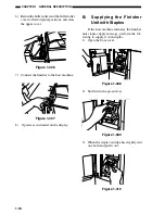
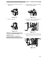
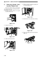
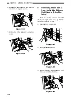
4) Hold the empty staple case on its sides, and
slide it out.
Figure 1-311
5) Set a new staple case.
Figure 1-312
Reference:
You may set no more than one staple
cartridge at a time.
Make sure that the new cartridge is one
specifically designed for the finisher unit.
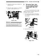
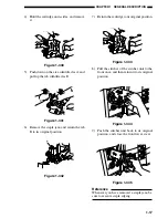
6) Pull the length of tape (used to hold the
staples in place) straight out.
Figure 1-313
7) Push in the stapler unit until the green le-
ver returns to its original position.
Figure 1-314
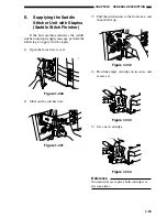
8) Check to make sure that the stapler has
been locked in place, and close the front
cover.
Figure 1-315
Summary of Contents for MJ-1027
Page 1: ...SERVICE MANUAL FINISHER MJ 1027 1028 File No SME040041A0 R04102169300 TTEC Ver01_2007 09 ...
Page 5: ...ii ...
Page 9: ...vi ...
Page 70: ...2 41 CHAPTER 2 FINISHER UNIT BASIC OPERATION Height sensor PS1 Paper Figure 2 240 ...
Page 101: ...3 15 CHAPTER 3 SADDLE STITCHER UNIT BASIC OPERATION Figure 3 301 ...
Page 104: ...3 18 CHAPTER 3 SADDLE STITCHER UNIT BASIC OPERATION 2 A3 LD Paper Path 3 sheets Figure 3 303 ...
Page 116: ...3 30 CHAPTER 3 SADDLE STITCHER UNIT BASIC OPERATION Cam Mount Figure 3 404 ...
Page 173: ...6 CHAPTER 6 TROUBLESHOOTING II ARRANGEMENT OF ELECTRICAL PARTS A Finisher Unit ...
Page 235: ...2 17 2 HIGASHIGOTANDA SHINAGAWA KU TOKYO 141 8664 JAPAN ...

