6-
CHAPTER 6 TROUBLESHOOTING
07/09
I. ADJUSTMENTS
Note
Before performing each adjustment, make
sure that all covers (incl. those of the finisher
and host machine) are closed. Otherwise, the
power is not supplied to the finisher and the
adjustment may not be performed properly.
A. Electrical System (finish-
er unit)
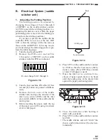
. Adjusting the Height Sensor (PS)
Perform the following adjustments
whenever you have replaced the finisher con
-
troller PCB or the height sensor (PS1).
1) Turn the host machine OFF.
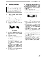
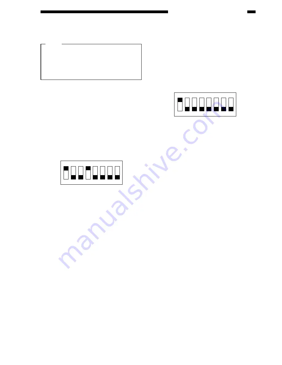
2) Set SW3 on the finisher controller PCB
as indicated.
ON
1
2
3
4 5
6
7
8
Figure 6-0
3) Turn the host machine ON while [0] but-
ton and [8] button are pressed simultane-
ously.
4) Place a paper on the tray.
5) Press SW1 on the finisher controller
PCB. This causes the finisher to execute
automatic adjustment, in which the tray
unit will shift.
• At the end of adjustment, trays will re-
turn to their home positions.
• During adjustment, LED1 flashes. At the
end of adjustment, LED1 turns and re-
mains ON.
• If automatic adjustment fails, the mecha-
nism stops while the tray in question is
being adjusted (at the same time, LED1
turns OFF).
6) Shift all bits on SW3 to OFF, and turn
OFF the host machine once.
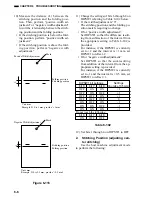
2. Adjusting the Alignment Position
If you have replaced the finisher control
-
ler PCB or if an alignment fault occurs, adjust
as follows. Performing the steps will affect
all paper sizes.
1) Turn the host machine OFF.
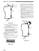
2) Remove the rear cover of the finisher
unit.
3) Set SW3 of the finisher controller PCB as
indicated.
ON
1
2
3
4 5
6
7
8
Figure 6-02
4) Turn the host machine ON while [0] but-
ton and [8] button are pressed simultane-
ously.
5) If you are using A4 paper, press SW1 on
the finisher controller PCB. If you are us
-
ing LT paper, press SW2 on the finisher
controller PCB.
• Pressing SW1/2 will open the swing
guide and cause the alignment plate to
move to A4/LT positions.
6) Place 10 sheets of A4/LT paper between
the alignment plate and the guide plate,
butting them against the stoppers.
7) Press SW1 or SW2 on the finisher con
-
troller PCB, and butt the alignment plate
against the sheets.
• Pressing SW1 will shift the alignment
plate to the front in 0.35 mm increments.
• Pressing SW2 will shift the alignment
plate to the rear in 0.35 mm increments.
Summary of Contents for MJ-1027
Page 1: ...SERVICE MANUAL FINISHER MJ 1027 1028 File No SME040041A0 R04102169300 TTEC Ver01_2007 09 ...
Page 5: ...ii ...
Page 9: ...vi ...
Page 70: ...2 41 CHAPTER 2 FINISHER UNIT BASIC OPERATION Height sensor PS1 Paper Figure 2 240 ...
Page 101: ...3 15 CHAPTER 3 SADDLE STITCHER UNIT BASIC OPERATION Figure 3 301 ...
Page 104: ...3 18 CHAPTER 3 SADDLE STITCHER UNIT BASIC OPERATION 2 A3 LD Paper Path 3 sheets Figure 3 303 ...
Page 116: ...3 30 CHAPTER 3 SADDLE STITCHER UNIT BASIC OPERATION Cam Mount Figure 3 404 ...
Page 173: ...6 CHAPTER 6 TROUBLESHOOTING II ARRANGEMENT OF ELECTRICAL PARTS A Finisher Unit ...
Page 235: ...2 17 2 HIGASHIGOTANDA SHINAGAWA KU TOKYO 141 8664 JAPAN ...


