6-3
CHAPTER 6 TROUBLESHOOTING
07/09
4. Adjusting the Buffer Roller Wind-
ing Amount
Perform this adjustment in the following
instances:
a. When the finisher controller PCB or the
EEPROM (Q2) on the finisher controller
PCB has been replaced
b. When something causes the winding
amount to fluctuate
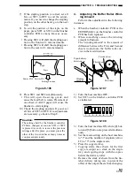
The "winding amount" is the amount of
difference between the First and Second
sheets wound onto the buffer roller de-
vice in the feed direction.
Paper delivery
direction
First sheet
Second sheet
Third sheet
Winding
amount
Figure 6-07
1) Turn the host machine OFF.
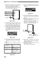
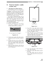
2) Set SW3 on the finisher controller PCB
as indicated.
ON
1
2
3
4 5
6
7
8
Figure 6-08
3) Turn the host machine ON while [0] but-
ton and [8] button are pressed simultane-
ously.
4) Set the mode setting on the host machine
to "1" and the number of originals (A4 or
LT) to "3" in the staple mode.
5) Press the copy start key.
• Copying starts, three sheets for the first
copy are output as a stack on the staple
tray, and copying stops with the copies
held at the delivery roller.
6) Remove the stack of sheets from the fin
-
isher delivery taking care to prevent the
offset of the output sheets from changing.
7) If the stapling position is correct, set all
bits on SW3 to OFF to end the adjust-
ments. If you need to change the stapling
position, on the other hand, go to the next
step.
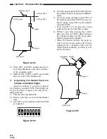
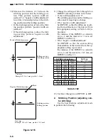
8) To suit the position of the staple on the
paper, press SW1 or SW2 on the finisher
controller PCB as many times as neces-
sary.
• Pressing SW1 will shift the stapling posi-
tion to the front in 0.3 mm increments.
• Pressing SW2 will shift the stapling posi-
tion to the rear in 0.3 mm increments.
Shift by SW2
Shift by SW1
Feeding direction
Staple
Paper
291±2mm (A4)/
273±2mm (LT)
Figure 6-06
9) Press SW1 and SW2 simultaneously.
• This will open the swing guide, and
cause the feed belt to rotate. Placement of
one sheet of A4/LT paper will cause the
finisher to start stapling.
10) Check the stapling position. If good, set
all bits of SW3 to OFF. If re-adjustments
are necessary, go back to Step 8.
Caution:
The settings held by the finisher controller
PCB are changed as soon as SW1 or SW2
is pressed. As such, to recover the previous
settings after the press, you must press the
other of the two switches as many times as
you pressed previously.
Summary of Contents for MJ-1027
Page 1: ...SERVICE MANUAL FINISHER MJ 1027 1028 File No SME040041A0 R04102169300 TTEC Ver01_2007 09 ...
Page 5: ...ii ...
Page 9: ...vi ...
Page 70: ...2 41 CHAPTER 2 FINISHER UNIT BASIC OPERATION Height sensor PS1 Paper Figure 2 240 ...
Page 101: ...3 15 CHAPTER 3 SADDLE STITCHER UNIT BASIC OPERATION Figure 3 301 ...
Page 104: ...3 18 CHAPTER 3 SADDLE STITCHER UNIT BASIC OPERATION 2 A3 LD Paper Path 3 sheets Figure 3 303 ...
Page 116: ...3 30 CHAPTER 3 SADDLE STITCHER UNIT BASIC OPERATION Cam Mount Figure 3 404 ...
Page 173: ...6 CHAPTER 6 TROUBLESHOOTING II ARRANGEMENT OF ELECTRICAL PARTS A Finisher Unit ...
Page 235: ...2 17 2 HIGASHIGOTANDA SHINAGAWA KU TOKYO 141 8664 JAPAN ...

