6-28
CHAPTER 6 TROUBLESHOOTING
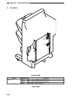
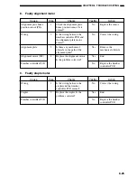
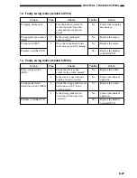
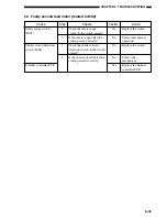
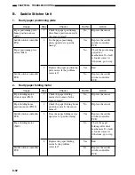
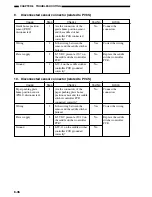
14. Faulty swing motor (related to PI20)
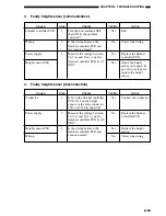
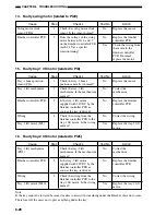
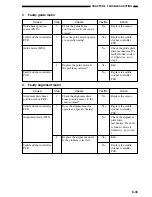
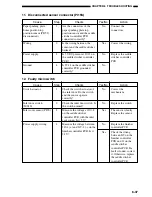
15. Faulty tray-1 lift motor (related to PI8)
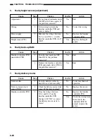
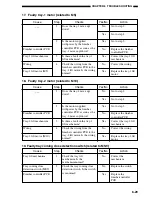
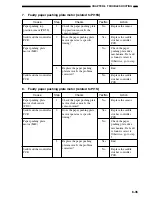
16. Faulty tray-2 lift motor (related to PI25)
Checks
Check the swing motor clock
sensor. Is the sensor normal?
Does the voltage of the swing
motor between J11-6 and -7
on the finisher controller PCB
reach 24 V at a specific
rotation timing?
Cause
Swing motor clock
sensor (PI20)
Finisher controller PCB
Step
1
2
Yes/No
No
No
Yes
Action
Replace the sensor.
Replace the finisher
controller PCB.
Check the wiring from
the motor to the
finisher controller
PCB. If normal,
replace the motor.
Checks
Check the tray-1 home
position sensor. Is it normal?
Check the tray-1 lift
mechanism. Is the mechanism
normal?
Is the tray-1 lift motor
supplied with 24 VDC by the
finisher controller PCB as
soon as the tray is driven?
Check the wiring from the
finisher controller PCB to the
tray-1 lift motor. Is the wiring
normal?
Cause
Tray-1 home position
sensor (PI8)
Tray-1 lift mechanism
Finisher controller PCB
Wiring
Tray-1 lift motor (M5)
Step
1
2
3
4
Yes/No
No
No
No
No
Yes
Action
Replace the sensor.
Correct the
mechanism.
Replace the finisher
controller PCB.
Correct the wiring.
Replace the tray-1 lift
motor.
Checks
Check the tray-2 lift
mechanism. Is the mechanism
normal?
Is the tray-2 lift motor
supplied with 24 VDC by the
finisher controller PCB as
soon as the tray is driven?
Check the wiring from the
finisher controller PCB to the
tray-2 lift motor. Is the wiring
normal?
Cause
Tray-2 lift mechanism
(PI25)
Finisher controller PCB
Wiring
Tray-2 lift motor (M10)
Step
1
2
3
Yes/No
No
No
No
Yes
Action
Correct the
mechanism.
Replace the finisher
controller PCB.
Correct the wiring.
Replace the tray-2 lift
motor.
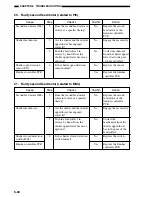
Note :
If the tray cannot be lowered because it makes contact with something under the Finisher, this error occurs.
Therefore, tell the users not to place anything under the tray.
Summary of Contents for MJ-1027
Page 1: ...SERVICE MANUAL FINISHER MJ 1027 1028 File No SME040041A0 R04102169300 TTEC Ver01_2007 09 ...
Page 5: ...ii ...
Page 9: ...vi ...
Page 70: ...2 41 CHAPTER 2 FINISHER UNIT BASIC OPERATION Height sensor PS1 Paper Figure 2 240 ...
Page 101: ...3 15 CHAPTER 3 SADDLE STITCHER UNIT BASIC OPERATION Figure 3 301 ...
Page 104: ...3 18 CHAPTER 3 SADDLE STITCHER UNIT BASIC OPERATION 2 A3 LD Paper Path 3 sheets Figure 3 303 ...
Page 116: ...3 30 CHAPTER 3 SADDLE STITCHER UNIT BASIC OPERATION Cam Mount Figure 3 404 ...
Page 173: ...6 CHAPTER 6 TROUBLESHOOTING II ARRANGEMENT OF ELECTRICAL PARTS A Finisher Unit ...
Page 235: ...2 17 2 HIGASHIGOTANDA SHINAGAWA KU TOKYO 141 8664 JAPAN ...

