


Engine Maintenance
92
4. Use a feeler gauge to check the valve
clearance on both valves for the number one
cylinder, the intake valve for the number two
cylinder, and the exhaust valve for the number
three cylinder. The valve clearance for both
the intake valve and the exhaust valve should
be 0.006 to 0.010 in. (0.15 to 0.25 mm).
NOTE: Check to make sure that the valve
stem cap is in good condition and is
positioned squarely on the top of the valve
stem. Replace the valve stem cap if it shows
significant wear.
5. Adjust the valves if necessary by loosening
the locknut and turning the adjustment screw
until the valve clearance is correct.
6. Hold the adjustment screw in place and
tighten the locknut.
Figure 81: Adjusting the Valve Clearance
7. Recheck the valve clearance.
8. Rotate the engine one full turn (360°) in the
normal direction of rotation (clockwise
viewed from the water pump end), and align
the 1-4 timing mark on the flywheel with the
index mark in the timing mark access hole.
This is top dead center of the compression
stroke for the number four cylinder.
9. Check and adjust the exhaust valve for the
number two cylinder, the intake valve for the
number three cylinder, and both valves for the
number four cylinder.
10. Replace the rocker arm cover, the cover for
the timing mark access hole, and tighten the
fuel injection lines when finished.
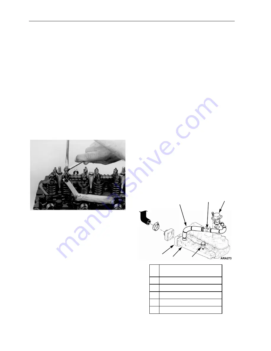
Crankcase Breather
The crankcase breather is located on top of the
rocker arm cover. The crankcase breather system
ducts crankcase gases formed in the crankcase
directly to the air intake. Harmful vapors that
would otherwise collect in the crankcase and
contaminate the oil, or escape to the outside, are
drawn back into the engine and burned. A
restrictor is placed in the breather hose to limit the
flow gas flow from the crankcase to the air intake
and keep the crankcase pressure from getting too
low.
Normal crankcase pressures with a new air
cleaner are 5 to 10 in. (127 to 254 mm) H
2
O of
vacuum at 1450 rpm and 7 to 11 in. (178 to
279 mm) H
2
O of vacuum at 2200 rpm. The
vacuum will increase as the air cleaner gets dirty
and becomes more restrictive. The crankcase
breather and the breather hose should be inspected
when the air cleaner element is replaced to make
sure they are not plugged or damaged.
NOTE: The breather hose must be routed so it
slopes down from the crankcase breather to the
intake manifold. This prevents condensation
from collecting in the breather hose. The
condensation can plug the breather hose if it
collects and freezes in the hose.
AEA705
1.
Insulation (Covers breather Hose
to prevent freezing.)
2.
Restrictor
3.
Crankcase Breather
4.
Air Restriction Indicator
5.
Intake Manifold
6.
Intake Air Heater
Figure 82: Crankcase Breather
2
3
4
5
1
6
Summary of Contents for SB-210
Page 4: ...4 ...
Page 12: ...List of Figures 12 ...
Page 31: ...Unit Description 31 Unit Photos Figure 6 Front View AJA1617 ...
Page 36: ...Unit Description 36 ...
Page 49: ...Operating Instructions 49 Figure 32 Viewing Sensors Screen Sequence ...
Page 54: ...Operating Instructions 54 Figure 40 Datalogger Screen Sequence ...
Page 101: ...Engine Maintenance 101 ...
Page 102: ...Engine Maintenance 102 ...
Page 140: ...Electric Standby Diagnosis 140 ...
Page 150: ...Index 150 ...
Page 152: ...Wiring Diagram Index 152 ...
Page 153: ...153 Model 30 and 50 Schematic Diagram Page 1 of 3 ...
Page 154: ...154 Model 30 and 50 Schematic Diagram Page 2 of 3 ...
Page 155: ...155 Model 30 and 50 Schematic Diagram Page 3of 3 ...
Page 156: ...156 Model 30 and 50 Wiring Diagram Page 1 of 4 ...
Page 157: ...157 Model 30 and 50 Wiring Diagram Page 2 of 4 ...
Page 158: ...158 Model 30 and 50 Wiring Diagram Page 3 of 4 ...
Page 159: ...159 Model 30 and 50 Wiring Diagram Page 4 of 4 ...


