


Engine Maintenance
90
b. Momentarily energize the pull-in coil by
placing a jumper between the white wire
(8DP—pin B) in the fuel solenoid
connector and the positive battery
terminal. The fuel solenoid should make a
definite click when the pull-in coil is
energized, but should not click when the
pull-in coil is de-energized.
c. De-energize the hold-in coil by removing
the jumper from the red wire (8D—pin A)
and the 2 terminal. The fuel solenoid
should make a definite click when the
hold-in coil is de-energized.
d. If the hold-in coil does not function
properly, check the resistance of the
hold-in coil by placing an ohmmeter
between the red wire (8D—pin A) and the
black wire (CH—pin C) in the fuel
solenoid connector. The resistance of the
hold-in coil should be 24 to 29 ohms. If
the resistance of the hold-in coil is not in
this range, replace the fuel solenoid.
Fuel Solenoid Replacement
1. Disconnect the fuel solenoid wire connector
from the main wire harness and remove the
old fuel solenoid.
2. Connect the new fuel solenoid wire connector
to the main wire harness.
3. Press the
O
N
key to turn the unit on.
4. Use the microprocessor keypad to enter the
Interface Board Test Mode. Refer to the
appropriate Microprocessor Diagnostic
Manual for specific information about the
Relay Test Mode.
5. Energize the fuel solenoid by energizing the
run relay with the Interface Board Test Mode.
NOTE: The fuel solenoid must be energized
when it is installed. If not, the plunger and
the linkage may not line up correctly and the
fuel solenoid will not function properly.
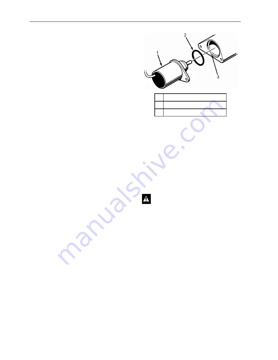
6. Place the O-ring in the groove in the end of
the fuel injection pump. Make sure that the
O-ring is positioned correctly during
installation to avoid damage and leaks.
7. Install the new fuel solenoid.
8. Press the
O
FF
key to turn the unit off after
installing the fuel solenoid.
Engine Valve Clearance Adjustment
1. Remove the rocker arm cover.
2. Remove the round cover (plug) from the
timing mark access hole on the front of the
bell housing.
3. Place the engine at top dead center of the
compression stroke for the number one
cylinder. Refer to steps a. through d.
a. Rotate the engine in the normal direction
of rotation (clockwise viewed from the
water pump end) until the 1-4 timing mark
on the flywheel lines up with the index
mark in the timing mark access hole.
1.
Fuel Solenoid
2.
O-ring
3.
Groove in Fuel Injection Pump
Figure 79: Fuel Solenoid Components
CAUTION: Loosen all of the injection
lines at the injection nozzles to prevent the
possibility of the engine firing while it is
being rotated.
AEA635
Summary of Contents for SB-210
Page 4: ...4 ...
Page 12: ...List of Figures 12 ...
Page 31: ...Unit Description 31 Unit Photos Figure 6 Front View AJA1617 ...
Page 36: ...Unit Description 36 ...
Page 49: ...Operating Instructions 49 Figure 32 Viewing Sensors Screen Sequence ...
Page 54: ...Operating Instructions 54 Figure 40 Datalogger Screen Sequence ...
Page 101: ...Engine Maintenance 101 ...
Page 102: ...Engine Maintenance 102 ...
Page 140: ...Electric Standby Diagnosis 140 ...
Page 150: ...Index 150 ...
Page 152: ...Wiring Diagram Index 152 ...
Page 153: ...153 Model 30 and 50 Schematic Diagram Page 1 of 3 ...
Page 154: ...154 Model 30 and 50 Schematic Diagram Page 2 of 3 ...
Page 155: ...155 Model 30 and 50 Schematic Diagram Page 3of 3 ...
Page 156: ...156 Model 30 and 50 Wiring Diagram Page 1 of 4 ...
Page 157: ...157 Model 30 and 50 Wiring Diagram Page 2 of 4 ...
Page 158: ...158 Model 30 and 50 Wiring Diagram Page 3 of 4 ...
Page 159: ...159 Model 30 and 50 Wiring Diagram Page 4 of 4 ...


