


Page 37
Apr-21-2016 DI-602A 320 DS (NZ313)_UL_April 2016
Texmate, Inc. Tel. (760) 598-9899 • www.texmate.com
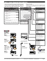
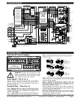
Rear Panel Pinout Diagram
32
31
30
29
28
27
26
25
17
16
14
15
8
9
10
11
Input Module
(See I-Series Input Module
Guide for Connection Details)
1
2
3
4
5
6
22 21 20
23
18
12
AC/DC POWER
Dual Analog
Output ONLY
19
24
Relay Outputs
Serial Output
Function Pins
LOCK
HOLD
TEST
COM CAPTURE
Analog Output
NOTE:
The meter uses plug-in type screw terminal connectors for most input
and output connections and an RJ-6 phone connector for the optional RS-232 or
RS-485 serial outputs.
Input Signal – Pins 1 to 6
See the
I-Series Input Modules Guide (Z87)
for connection
details of all input modules. On most single input signal condi-
tioners, usually Pin 1 is the signal high pin (Hi +) and Pin 3 is
the signal low pin (Lo –).
Function Pins – Pins 8 to 15
Pin 8 – Program Lock
. By connecting the PROGRAM LOCK pin
to the COMMON pin (pin 11 on the main PCB), the PROGRAM
LOCK pin allows the meter's programmed parameters to be
viewed but not changed.
Pin 9 – Hold Reading
. By connecting the HOLD READING pin
to the COMMON pin (pin 11), the HOLD READING pin allows the
DISPLAY BOARD
SP1
SP2
SP3
SP4
SP5
SP6
F1
PROG
UP
DOWN
F2
47K
47K
10n
0.01
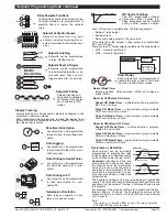
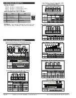
There are input
modules for almost
any input signal.
Input and Output
pins vary for
different modules.
Smart Modules
incorporate their own
A / D converters and
communicate digitally
with the meter.
See section on
I-Series Input Modules
for connection details.
17 Bit
Dual Slope
A/D
Converter
VREF-
Cref
Comp
A
B
VREF+
Caz Buf
Cint
Input Lo
Input Hi
+5VDC
+5V
-5V
-5VDC
MUX0
24V ISO RTN
+24VDC EXC
ANALOG COMMON
REFERENCE HI
SYSTEM GROUND
MUX1
F2(A)
D3
CAPTURE
F2(B)
HOLD
D1
D2
INPUT MODULES
PROCESSOR BOARD
3
4
5
6
7
Program Lock
Note:
External switches
are shown for the
purpose of illustration
only.
8
1
2
Display Test
Micro Reset
Common
AC Neutral,
– DC
AC Line,
+ DC
GND
Isolated
GND
A / TXD
B / RXD
Reading Hold
1
2
3
4
1
2
Volts
mA
HEADER
2
3
4
5
2
3
Chassis Ground Tab for Optional Metal Case
1
5
Capture
Isolated
+5VDC
1
2
3
4
5
6
7
8
9
10
11
12
13
14
15
16
17
18
1 3 5 7 9 11 13 15 17
2 4 6 8 10 12 14 16 18
Socket for Input Signal
Conditioning Module
Common
Mode Line
Choke
Bridge
Rectifier
PTC for HI Voltage
Fuse for LO Voltage
Isolated Feed Back
Isolated
Switching
Power
Supply
Controller
-5 VDC
+18 VDC ISO
–
+5 VDC
+5 VDC
+5 VDC
GND
+24 VDC
GND
LC Filter
+
1
2
3
4
5
6
7
8
9
10
RELAY MODULES
NO3
COM 1 & 3
NO1
NC1
NO4
COM 2 & 4
NO2
NC2
MOV's
9A
4A
+ 5 V
SP3
+ 5 V
SP1
MOV's
9A
4A
+ 5 V
SP4
+ 5 V
SP2
MicroProcessor
Flash RAM
FeRAM
EEPROM
Optional Real-
Time Clock
& 15 Year
Lithium Battery
+5VDC
GND
1 Reserved
6 Reserved
+ O/P 2
- Common
+ O/P 1
ANALOG
OUTPUT
+5VDC
+5VDC
+5VDC Isolated
+18V
ISO
Isolated -5VDC
+5VDC
+
Isolated
RS232 or
RS485
Isolated
Analog
Output
Dual
or Single
ANALOG OUTPUT
SERIAL OUTPUT
MAIN BOARD
24V ISO RTN
GND
GND
GND
Output pins vary for different relay output
modules. Up to 26 pins can be used
CARRIER BOARD
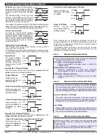
+
TERMINAL 1
Pins 1 up to 16
TERMINAL 2
AC / DC POWER
TERMINAL 4
TERMINAL 5
TERMINAL 6
Relay Example: OR14
Functional Diagram
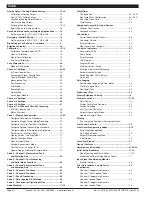
Connector Pinouts
Connector Pinouts
meter's display to be frozen. However, A/D conversions continue
and as soon as pin 9 is disconnected from pin 11 the updated
reading is instantly displayed.
Pin 10 – Display Test and Reset
. The DISPLAY TEST and
RESET pin provides a test of the meter's display and resets the
microprocessor when the DISPLAY TEST and RESET pin is con-
nected to the COMMON pin (pin 11).
Pin 11 – Common
. To activate the HOLD, TEST and RESET, or
LOCKOUT pins from the rear of the meter, the respective pins have
to be connected to the COMMON pin.
Pins 14/15 – AC/DC Power Input
. These are the pins that supply
power to the meter. See Power Supply for details of the standard
and optional low voltage power supply.
Chassis Ground Tab
. Only on versions with metal sheath casing.
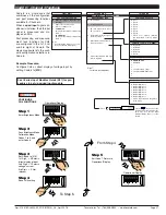
Pin Socket
Part Numbers:
93-PLUG2P-DR.....2 pins
93-PLUG3P-DR.....3 pins
93-PLUG4P-DR.....4 pins
93-PLUG5P-DR.....5 pins
93-PLUG6P-DR.....6 pins
Right-angled
Screw Terminal Plug
Pin Socket
Input Power
Screw Terminal Plug
Part No: 93-PLUG2P-DP
Part Number:
93-PLUG2P-SP
Pin Socket
Straight-thru Input Power
Screw Terminal Plug
Part Numbers:
93-PLUG2P-DS....2 pins
93-PLUG3P-DS....3 pins
93-PLUG4P-DS....4 pins
Pin Socket
Straight-thru
Screw Terminal Plug
Part Number:
93-PLUG5PS
Part Number:
93-PLUG8PS
Pin Socket
Pin Socket
Part Numbers:
93-PLUG2PS.....2 pins
93-PLUG3PS.....3 pins
93-PLUG5PS.....5 pins
93-PLUG8PS.....8 pins
3.5mm Pitch Screw Terminal Plugs
for Smart Modules
!
WARNING
:
AC and DC input signals and power supply
voltages can be hazardous. Do Not connect live wires to
screw terminal plugs, and do not insert, remove or handle
screw terminal plugs with live wires connected.


