


Texmate, Inc. Tel. (760) 598-9899 • www.texmate.com
Page 12
Apr-21-2016 DI_602A 320 DS (NZ313)_April 2016
Display Configuration
Once you have read the user manual and related supplements,
and installed and powered-up the meter, configure the display
to suit its designated application.
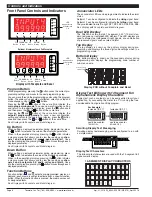
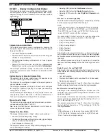
Display Brightness Mode
The
display brightness mode
is accessed when entering the
main programming mode. It allows you to adjust the brightness
of the display LEDs and setpoint annunciators without interfer-
ing with other configuration settings. It is always available, even
with the PROGRAM LOCK switch set to ON, or the external
LOCK pin connected to the COMMON pin, locking out the
programming modes.
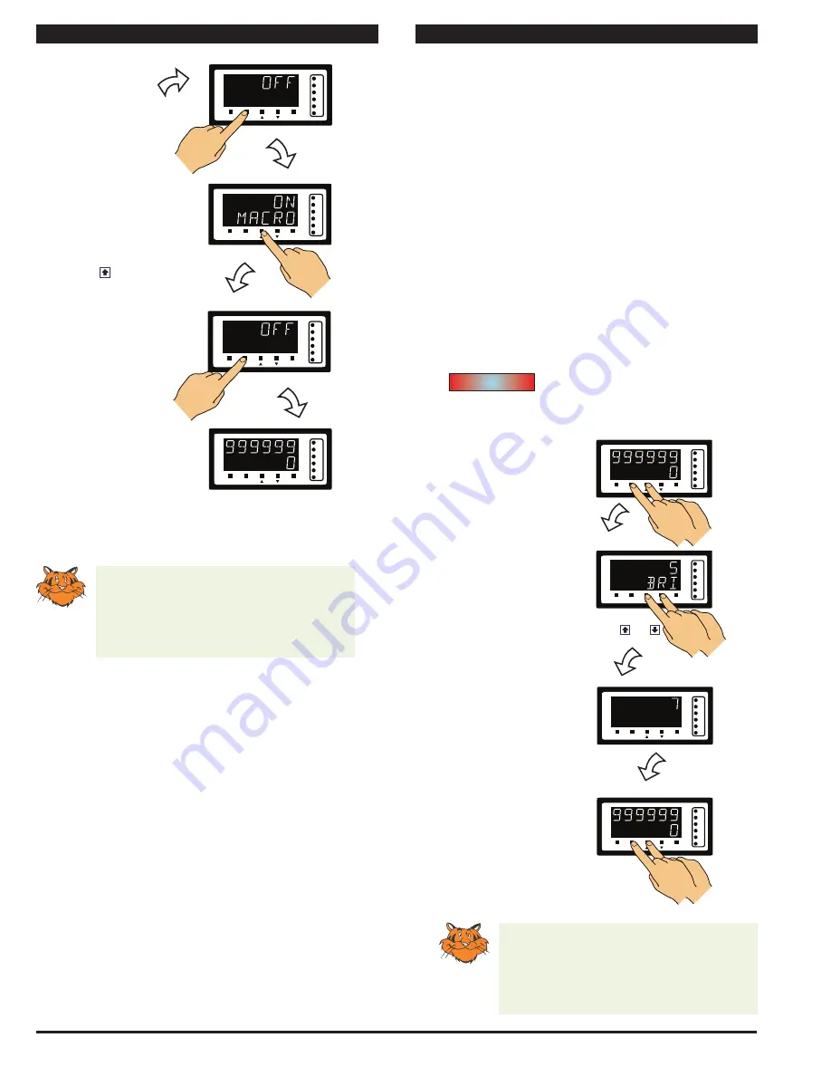
The display brightness can be set between 0 and 7, with 0
being dull and 7 being bright. The default setting is 5.
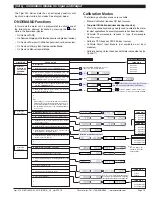
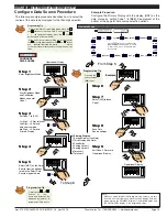
DISPLAY
BRIGHTNESS
MODE
Step 1
Step 2
Step 3
Save brightness setting.
Exit Brightness Mode.
Return to Operational
Display
Example
Enter Brightness Mode
Adjust brightness to 7
OR
SP1
SP3
SP4
SP5
SP6
SP2
F1
P
F2
Operational Display
Press
at same
time
SP1
SP3
SP4
SP5
SP6
SP2
F1
P
F2
SP1
SP3
SP4
SP5
SP6
SP2
F1
P
F2
SP1
SP3
SP4
SP5
SP6
SP2
F1
P
F2
Operational Display
Press
at same
time
Example Procedure:
Configure the display brightness (contrast) setting to 7 (bright).
Programming Tip
The
Display Brightness
setting procedure
can be performed at any time without inter-
fering with other configuration settings by
entering the main programming mode.
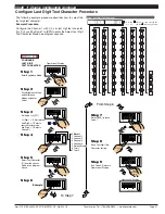
START HERE
[bri] - Display Brightness
Initial Setup Procedures
Initial Setup Procedures continued
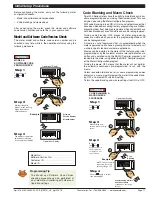
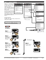
Programming Tip
Code Blanking and Macro ON/OFF set-
tings revert to the meter’s original configu-
ration settings when the meter is powered
off and on.
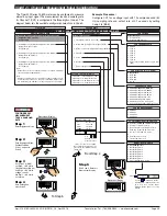
Step 5
Step 7
Example
Press the Prog. button
Press the Prog. button.
NOTE: Unless otherwise
requested, the factory
default setting is oFF
Step 6
Press the button to switch
the macro OFF
continued from Step 4
Macro
SP1
SP3
SP4
SP5
SP6
SP2
F1
P
F2
Press
1
SP1
SP3
SP4
SP5
SP6
SP2
F1
P
F2
Press
1
SP1
SP3
SP4
SP5
SP6
SP2
F1
P
F2
Press
1
SP1
SP3
SP4
SP5
SP6
SP2
F1
P
F2
Operational Display


