


Texmate, Inc. Tel. (760) 598-9899 • www.texmate.com
Page 2
Apr-21-2016 DI_602A 320 DS (NZ313)_April 2016
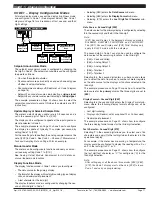
Development System for Custom
Macros
The Tiger 320 Macro Development System, which may
be downloaded free from our website, can be used to
create powerful macro software that allows Tiger 320 T
Versions to be easily customized to suit any proprietary
OEM application.
Installed Application Software
Includes
Counter Functions:
Two built-in counters. UP count-
ers, DOWN counters, UP/DOWN counters and high
speed quadrature counters.
Data Logging:
Logging with a date/time stamp, initi-
ated at timed intervals, by activation of a setpoint, or
manually. Data stored in internal 1MB EEPROM or in
a removable 4 to 128M Flash Card Memory Module.
Endless loop recording is supported.
Input Compensation:
Provides compensation to the
primary input channel (CH1) via channels 2, 3 or 4.
Linearization:
4 selectable 32 point or one 125 point
flexible linearization tables are provided.
Logic I/O:
28 Macro programmable I/O ports support-
ed.
Manual Loader:
Front panel adjustable, 4 to 20mA or
0 to 10V isolated analog output.
Math Functions:
Cross channel math functions to
calculate the sum, difference, ratio or the product of two
inputs.
On Demand Functions:
Tare, compensation and cal-
ibration.
Peak and Valley:
The meter can retain peak and valley
(min/max) information and recall this on the front panel.
Remote Setpoint Input:
Remote setpoint input via
channel 2.
Serial Output Protocols:
Selectable communication
modes include ASCII, Modbus (RTU), Master Mode (for
meter to meter communication) and an Epson compat-
ible printer driver. An Ethernet optional output carrier
board is also supported.
Setpoint Functions:
Six super smart setpoints with
fully configurable hysteresis, on and off delays, one
shot, pulse and repeat timers, latching, dual PID, set-
point tracking, resetting of registers, initiating of logging
and printing.
Signal Conditioning Functions:
Averaging, smart
filter, rounding, square root,auto zero maintenance.
Timer:
Timer functions supported in either time-up,
time-down, or real-time clock modes.
Totalizer:
Two totalizers for running total and batch
totals of a process signal that can be accumulated over
time.
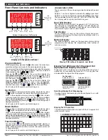
Display
Digital Display:
14-segment alphanumeric, 0.39” (10
mm) LEDs.
Display Color:
Red (std) and/or Green (optional).
Digital Display Range:
-199999 to 999999
Update Rate:
3 to 10 times per second
Display Dimming:
8 brightness levels. Front Panel
selectable
Scrolling Display Text Messaging:
Full alphanumeric
text characters supported on T Version with macros.
Polarity:
Assumed positive. Displays - negative
Decimal Point:
Front panel, user selectable to five
positions.
Annunciators:
6 red LEDs on front panel; one per
setpoint.
Overrange Indication:
Underrange Indication:
Front Panel Controls:
PROGRAM, UP and DOWN
(F1 and F2 available on T version only).
Operating System
(Tiger 320)
Processor:
32 bit with floating point maths (18.4 MHz).
Flash Memory:
64k, 4k for use by custom macros.
RAM:
1.25k and FeRAM 4k.
EEPROM:
E Version 4k standard, T Version 32k stan-
dard. Memory upgrades available to 32k for LIN Tables
and 1MB for Data Logging and custom macros.
Registers:
6144 registers comprised of 8, 16 or 32
bit signed, unsigned or floating point registers, imple-
mented in a combination of RAM, FeRAM, Flash and
EEPROM.
Internal communication BUS:
32 bit I2C BUS
Real Time Clock (option):
Year:Month:Date:Hour:Minute:Second with 15 yr
Lithium battery backup.
Configuration:
Supports Front Panel Programming
Codes and a PC-based Configuration Utility Program,
which may be downloaded free from our website. T
Version also supports custom macros.
Specifications


