Texmate Tiger 320 DI-602AE Manual Download Page 3

Page 3

Apr-21-2016 DI-602A 320 DS (NZ313)_UL_April 2016

Texmate, Inc. Tel. (760) 598-9899  •  www.texmate.com

Specifications

Inputs


Inputs Available:  

More than 120 single, dual, triple 

and quad input signal conditioners available covering all 

types of analog, digital and mixed input signals.

Accuracy:  

Tiger 320 PMCs enable the user to estab-

lish any degree of system accuracy required.  Built-in 

compensation and linearization functions enable sys-

tem accuracies of the order of ±0.0001% of reading for 

analog inputs.  Stop -Start time resolution from ±1sec 

to ±0.7nsec.  Digital input and pulse counts ±1 count.

A/D Convertors:

  A Dual Slope, bipolar 17 bit A/D is 

provided as standard on the main board.  SMART mod-

ules can have 24 bit or 16 bit Delta-Sigma A/D conver-

tors that utilize the internal I2C BUS.

Temperature Coefficient:

  Typically 30ppm/˚C. 


Compensation can be utilized to achieve system tem-

perature coefficients of 1ppm.

Warm Up Time:

  Up to 10 minutes, depending on input 

module.

Conversion Rate:

  Typically 10 samples per second.  

However, SMART input modules are available that can 

convert at 60, 240, 480 or 960 samples per second.

Control Output Rate:

  Can be selected for 100msec or 

10msec.  Some SMART modules have SSR outputs that 

react within 1.2msec.

Excitation Voltage:

  Depends on input module select-

ed.  Typically, 5V, 10V or 24VDC is provided.
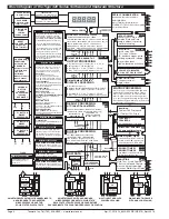
Outputs

(See pages 38-39 for pinouts and details of modular con-

struction)

Two Optional Plug-in Carrier Boards:  

Provide three dif-

ferent serial outputs or no serial output, support single 

or dual analog outputs, and accept any one of seven 

different plug-in I/O modules.


1. Standard Carrier Board:

  Is available without a serial 

output, or with either an isolated RS-232 or an isolated 

RS-485 (RJ-6 socket).

2. Ethernet Carrier Board:

  10/100Base-T Ethernet (RJ-

45 socket).

Two Isolated Analog Output Options:  

Mounted on any 

carrier board.

1. Single Analog Output:

  Fully scalable from 4 to 20mA 

or 0 to 20mA (or reverse) and selectable for 0 to 10VDC 

(or reverse).

2. Dual Analog Output:

  Fully scalable from 0 to 10VDC 

(or reverse). 

Outputs continued


Analog Output Specifications:

  Accuracy: 0.02% 

FS.  Resolution:  16-bit Delta-Sigma D/A provides 

0.4µA on current scaling, 250µV on voltage scaling.  

Compliance: 500

Ω

 maximum for current output. 


500

Ω

 minimum for voltage output.  Update Rate: 

Typical 7 per second.  Step Response: Typical 6msec 

to a display change.  Scalable: From 1 count to full 

scale. 

Seven I/O Modules:  

Plug into any carrier board from rear.


1. Four Relay Module:  

Available in six combinations from 

one relay up to a total of two 9/10A Form C Relays* and 

two 4/5A Form A Relays**.

2. Four Relay Module:  

Available with one to four 5A 

Form A Relays**.

3. Six Relay Module:  

Available with five or six 4A Form 

A Relays**.

*Form C Relay Specifications:  

9/10A 240VAC~1/2 

HP, 8A 24VDC.  Isolation 3000V.  UL and CSA listed.

**Form A Relay Specifications:  

4/5A 240VAC, 4A 

24VDC.  Isolation 3000V.  UL and CSA listed. 

4. Four Solid State Relay (SSR) Module:  

Available with 

one to four independent (210mA DC only) SSRs (300V 

max).

5. Six Output 5VDC / TTL or Open Collector:  

Available 

with 0 to 5VDC (50 mA) or 0 to V+ (5VDC max, 50 mA).

6. Opto Isolated I/O Module:  

Available in either 6 Outputs 

& 6 Inputs, or 16 Outputs and 6 Inputs.  For connection to 

an external breakout box.


7. Flash Card Memory Module:  

Available with 8 or 16 

MB memory.

Power Supplies

Auto sensing AC/DC (DC to 400Hz) hi volts std, low 

volts optional.

PS1 (standard):

  95-300VDC or 85-265VAC, 50-400Hz, 

2W nominal.

PS2 (optional):

  10-72VDC or 14-48VAC, 50-400Hz, 

2W nominal.

Environmental 

(See Rear page for IP-65 & NEMA-4 

options)

Operating Temperature:  

0 to 50 ˚C (32 ˚F to 122 ˚F).

Storage Temperature:

  -20 ˚C to 70 ˚C (-4 ˚F to 158 ˚F).

Relative Humidity:

  95% (non-condensing) at 40 ˚C 

(104 ˚F).

Mechanical 

(See Rear page for more details)

Case Dimensions:  

1/8 DIN, 96x48mm (3.78” x 1.89”)

Case Material:

  94V-0 UL rated self-extinguishing poly-

carbonate.

Weight:

  11.5 oz (0.79 lbs), 14 oz (0.96 lbs) when 

packed.

Certifications and Listings

CE:

  As per EN-61000-3/4/6 and EN-61010-1.

UL:

  E469078

Summary of Contents for Tiger 320 DI-602AE

Page 1: ...weighing applications Programmable input averaging and smart digital filtering for quick response to input signal changes Display text editing Customize display text for OEM applica tions Scrolling d...

Page 2: ...ts with fully configurable hysteresis on and off delays one shot pulse and repeat timers latching dual PID set point tracking resetting of registers initiating of logging and printing Signal Condition...

Page 3: ...ut Fully scalable from 4 to 20mA or 0 to 20mA or reverse and selectable for 0 to 10VDC or reverse 2 Dual Analog Output Fully scalable from 0 to 10VDC or reverse Outputs continued Analog Output Specifi...

Page 4: ...INVERSE OF INPUT LINEARIZATION LOG OF INPUT Bargraph display only RTD SAMPLE RATE SMART AUTO ZERO SQUARE ROOT THERMOCOUPLES DECIMALS RIGHT HAND CHARACTER AND ROUNDING FOR CH1 2 3 4 RESULT AND DEFAULT...

Page 5: ...Page 5 Apr 21 2016 DI 602A 320 DS NZ313 _UL_April 2016 Texmate Inc Tel 760 598 9899 www texmate com THIS PAGE INTENTIONALLY LEFT BLANK...

Page 6: ...When the function button is pressed the macro carries out its designated tasks See Display with Faceplate and Bezel diagram Annunciator LEDs The annunciator LEDs can be programmed to indicate the alar...

Page 7: ...the respective pins have to be connected to the COMMON pin pin 11 The LOCK pin can also be configured in Code 9 to carry out the fol lowing functions see Front Panel Programming Codes on Page 9 Reset...

Page 8: ...etting 000 is shown If an X appears in place of a digit this means that any number displayed in that digit is not relevant to the function being explained or more than one selection can be made SP1 SP...

Page 9: ...t 3 SP_3 Setpoint 4 SP_4 Setpoint 5 SP_5 Setpoint 6 SP_6 Enter these menus to adjust SP activation values Setpoint Relay Control Settings Mode P P P P P Setpoint 1 SPC_1 Setpoint 2 SPC_2 Setpoint 3 SP...

Page 10: ...function in the Calibration On Demand Mode press the P button for 4 seconds to activate one of the following selected on demand modes On Demand Modes Tare Single point calibration Two point calibrati...

Page 11: ...g are hidden preventing them from being reprogrammed Any codes that have not been blanked out are still visible and can be reprogrammed Turning code blanking OFF means all meter programming codes are...

Page 12: ...ness Mode Adjust brightness to 7 OR SP1 SP3 SP4 SP5 SP6 SP2 F1 P F2 Operational Display Press at same time SP1 SP3 SP4 SP5 SP6 SP2 F1 P F2 SP1 SP3 SP4 SP5 SP6 SP2 F1 P F2 SP1 SP3 SP4 SP5 SP6 SP2 F1 P...

Page 13: ...odule Note This function is not available on all input modules 5 Calibrate Analog Output requires multimeter con nected to pins 16 and 17 6 7 0 Serial Communications Properties 1 Set Auto Zero Mainten...

Page 14: ...1 to 255 samples The averaging window can be set to between 1 and 65535 counts See the calibration modes diagram on Page 13 showing a breakdown of 1st 2nd and 3rd digits See Input Signal Sampling Sho...

Page 15: ...P5 SP6 SP2 F1 P F2 Operational Display Press at same time SP1 SP3 SP4 SP5 SP6 SP2 F1 P F2 Press 1 OR SP1 SP3 SP4 SP5 SP6 SP2 F1 P F2 SP1 SP3 SP4 SP5 SP6 SP2 F1 P F2 Press 1 SP1 SP3 SP4 SP5 SP6 SP2 F1...

Page 16: ...g window settings Example INPUT SIGNAL 1st Digit 2 Selects related calibration functions 2nd Digit 2 Selects averaging samples for 3rd digit 3rd Digit 1 Selects CH1 for 2nd digit Enter Brightness Mode...

Page 17: ...in Code 1 CODE 1 Display Configuration Modes All meter display modes except the display brightness mode are configured in Code 1 See diagram below See Code 1 diagram on Page 18 for a breakdown of firs...

Page 18: ...e meter the values for setpoint 5 and setpoint 6 are activated as upper and lower limits See Analog Output Supplement for further details Note 1 LED annunciators are always off except when the meter i...

Page 19: ...re the Primary Display with the display diSP as the data source by setting Code 1 to X50 See diagram at the bottom of the page for data source selection options Configure Data Source Procedure The fol...

Page 20: ...SP5 SP6 SP2 F1 P F2 Press 1 0 No rounding 1 Rounding by 2 s 2 Rounding by 5 s 3 Rounding by 10 s Configure Display Format Mode Procedure LAST DIGIT ROUNDING DISPLAY UNITS 0 Decimal 1 24 hour clock mod...

Page 21: ...rational Display Press at same time SP1 SP3 SP4 SP5 SP6 SP2 F1 P F2 Press 2 OR SP1 SP3 SP4 SP5 SP6 SP2 F1 P F2 Press 1 SP1 SP3 SP4 SP5 SP6 SP2 F1 P F2 OR SP1 SP3 SP4 SP5 SP6 SP2 F1 P F2 Press 1 SP1 SP...

Page 22: ...and enter Code 2 SP1 SP3 SP4 SP5 SP6 SP2 F1 P F2 Operational Display Press at same time SP1 SP3 SP4 SP5 SP6 SP2 F1 P F2 Press 2 OR SP1 SP3 SP4 SP5 SP6 SP2 F1 P F2 Press 1 SP1 SP3 SP4 SP5 SP6 SP2 F1 P...

Page 23: ...TD 2 or 4 wire 3rd digit selects type of RTD 4 Frequency 5 Period 6 Counter 7 Smart Input Module CODE 2 CHANNEL 1 MEASUREMENT TASK AND SAMPLING RATE SMART INPUT MODULE 0 Output Register 1 1 Output Reg...

Page 24: ...me stamp Time stamp settings are configured in Code 8 Post processing functions refer to functions that occur to the input after it has been configured and scaled Example Procedure Configure the meter...

Page 25: ...st and 2nd digits of Code 4 The diagram opposite lists the available configuration selections in Code 4 Example Procedure Configure CH2 for a voltage input direct with no linearization by setting Code...

Page 26: ...ut by setting Code 5 to 11X FOR THERMOCOUPLE 0 Type J 1 Type K 2 Type R 3 Type S 4 Type T 5 Type B 6 Type N 7 Select user defined lineariza tion table Table 1 set up in CAL 24X FOR RTD TYPE 2 3 4 WIRE...

Page 27: ...le 3rd digit selects register FOR SMART INPUT MODULE 0 Output Register 1 1 Output Register 2 2 Output Register 3 3 Output Register 4 4 Output Register 5 5 Output Register 6 6 Output Register 7 7 Smart...

Page 28: ...Note 5 5 125 point Linearization on Result Tables 1 to 4 cascaded See Note 5 6 32 point Linearization on Result Tables 1 to 4 selected from the rear of the meter The selected table is not available if...

Page 29: ...ONS LOG OR PRINT TRIGGER 0 No trigger 1 Trigger on Demand from PROGRAM Button 2 Trigger on Demand from F1 Button 3 Trigger on Demand from F2 Button 4 Trigger on Demand from HOLD Pin 5 Trigger on Deman...

Page 30: ...of the meter and the selected input module Relay Output Modules Four standard relay output module options provide a selection of 16 relay configuration options for DI 50 meters Three electromechanica...

Page 31: ...s Setpoint Reset Trigger Setpoints can be programmed to reset selected registers or be manually reset They can also trigger a data print or a data log Dual PID SP PID Control Settings The PID proporti...

Page 32: ...Pulsed OFF Modes These are delay modes were the relay is normally on and pulses off when the setpoint activates 1 Shot OFF mode Programmable Minimum OFF time SP OFF SP ON 1 Shot OFF Mode Prog Min OFF...

Page 33: ...P F2 SP1 SP3 SP4 SP5 SP6 SP2 F1 P F2 SP1 SP3 SP4 SP5 SP6 SP2 F1 P F2 OR SP1 SP3 SP4 SP5 SP6 SP2 F1 P F2 Press 1 SP1 SP3 SP4 SP5 SP6 SP2 F1 P F2 Press 1 SP1 SP3 SP4 SP5 SP6 SP2 F1 P F2 SP1 SP3 SP4 SP5...

Page 34: ...rgized BELOW setpoint value with RISING INPUT SIGNAL INITIAL START UP INHIBIT SP Activation Source 0 Activate Setpoint Source from Selected Register 1 Select Source for Setpoint Note X1X is a register...

Page 35: ...0 to 6553 5 secs Reset SPC_X to XX0 DOM 0 0 to 6553 5 secs Minimum on time M_on 0 0 to 6553 5 secs On time on _t 0 0 0 001 to 6553 5 65 535 secs DOB 0 0 to 6553 5 secs Off time oFF_t 0 0 0 001 to 655...

Page 36: ...hold the button down while cycling through the decades and release it when oFF or tArE appears Registers that Should Not be Used The following registers are contained within the selectable 1 to 244 R...

Page 37: ...ltage Isolated Feed Back Isolated Switching Power Supply Controller 5 VDC 18 VDC ISO 5 VDC 5 VDC 5 VDC GND 24 VDC GND LC Filter 1 2 3 4 5 6 7 8 9 10 RELAY MODULES NO3 COM 1 3 NO1 NC1 NO4 COM 2 4 NO2 N...

Page 38: ...3 SP1 SP4 SP2 Relay Modules with up to two 4 5A Form A Relays and up to two 9 10A Form C Relays 32 31 30 28 29 27 26 25 Options Order Code OR51 OR52 OR53 OR54 210mA 210mA 210mA 210mA 210mA 210mA 210mA...

Page 39: ...and process control applications Modular construction ensures you don t have to pay for unnecessary hardware Simply order the input and output options to suit your application Input Signal Conditioni...

Page 40: ...optional Analog Output Module optional Relay Output Module and a Serial Output Module RS 232 RS 485 or No Serial Output Ethernet Output Carrier Board Is similar to the Standard Output Module Carrier B...

Page 41: ...noisy components Shielding cables for input output leads is recommended with shield connection to earth ground near the meter preferred 4 A circuit breaker or disconnect switch is required to disconne...

Page 42: ...Code 3 Channel 1 Post Processing and Serial Mode Functions 24 Code 4 Channel 2 Measurement Task and Sampling Rate 25 Code 5 Channel 3 Functions 26 Code 6 Channel 4 Functions 27 Code 7 Result Processi...

Page 43: ...d Not Be Selected 36 Resetting and Incrementing Using Setpoints 36 Relay Logic Output Modules 38 Serial Communication Configuration 24 Pinouts 38 Setpoint Programming Mode 30 35 Data Logging 31 Data P...

Page 44: ...om Texmate has facilities in Japan New Zealand Taiwan and Thailand Case Dimensions Clear Lockable NEMA 4X Splash Proof Cover P N OP N4 96x48 The 96x48mm case is particularly suitable for mounting in m...

Reviews: