


Page 23
Apr-21-2016 DI-602A 320 DS (NZ313)_UL_April 2016
Texmate, Inc. Tel. (760) 598-9899 • www.texmate.com
To Step 5
From Step 4
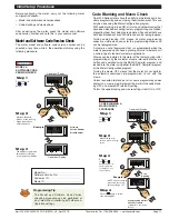
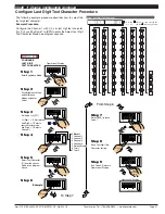
Step 1
Step 2
Step 3
Step 4
Step 5
Pass Brightness Mode,
Calibration Mode,
Code 1, and enter
Code 2
Set Code 2 to [000]
Exit Code 3. Return to
Operational Display
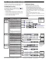
CONFIGURE CH1
1st Digit = 0 Selects
10 samples/sec (60 Hz)
2nd Digit = 0 Selects
voltage, current
3rd Digit = 0 Selects
no function
Enter Brightness Mode
MEASUREMENT
TASK & SAMPLING
RATE
Save setting and
enter Code 3
SP1
SP3
SP4
SP5
SP6
SP2
F1
P
F2
Operational Display
Press
at same
time
SP1
SP3
SP4
SP5
SP6
SP2
F1
P
F2
Press
3
OR
SP1
SP3
SP4
SP5
SP6
SP2
F1
P
F2
SP1
SP3
SP4
SP5
SP6
SP2
F1
P
F2
Press
at same
time
SP1
SP3
SP4
SP5
SP6
SP2
F1
P
F2
Operational Display
SP1
SP3
SP4
SP5
SP6
SP2
F1
P
F2
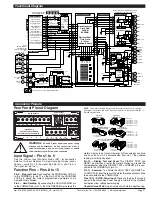
FOR VOLTAGE
0 No function
1 Peak detector
2 Pressure with Auto-cal
FOR THERMOCOUPLE
0 Type J
1 Type K
2 Type R
3 Type S
4 Type T
5 Type B
6 Type N
7 Select user defined table set up in CAL
[24X]
FOR RTD TYPE (2-, 3-, 4- WIRE)
0 Resistance
1 RTD 385
2 RTD 392
3 RTD 120
4 Cn 10
FREQUENCY RANGE
0 99.999 Hz range from 0.010 Hz
1 99.999 Hz range from 2.000 Hz
2 999.99 Hz range from 0.01 Hz
3 999.99 Hz range from 2.00 Hz
4 9999.9 Hz range from 0.1 Hz
5 9999.9 kHz range from 2.0 Hz
6 99 kHz range from 1 Hz (1 s gate)
7 655.35 kHz range from 10 Hz (0.1 s gate)
PERIOD MEASUREMENT
0 99.999 s
1 9.9999 s
2 999.99 ms
3 99.999 ms
COUNTER/RESIDENT TIMER/CLOCK
0 Counter input with 16 bit Pre-scaler
1 Setting of 16-bit Pre-scaler
2 Debounced Counter with Pre-scaler
3 Up/Down Counter with Pre-scaler
4 0.1 sec Timer with Pre-scaler
5 –
6 External 24-hour clock
7 Internal 24-hour clock
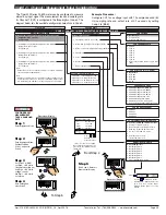
ANALOG SAMPLE RATE
MEASUREMENT TASK
0 Voltage, Current
1 TC (3rd digit selects type of TC)
2 RTD 3-wire (3rd digit selects type of RTD)
3 RTD 2- or 4-wire (3rd digit selects type of RTD)
4 Frequency
5 Period
6 Counter
7 Smart Input Module
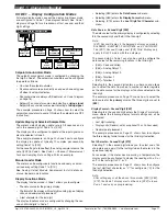
CODE 2 – CHANNEL 1 MEASUREMENT TASK AND SAMPLING RATE
SMART INPUT MODULE
0 Output Register 1
1 Output Register 2
2 Output Register 3
3 Output Register 4
4 Output Register 5
5 Output Register 6
6 Output Register 7
7 Smart Input Module Setup.
THIRD DIGIT
FIRST DIGIT
SECOND DIGIT
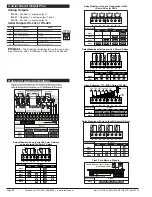
Example Procedure:
Configure CH1 for a voltage input with 10 samples/second (60
Hz) sampling rate and output rate of 0.1 seconds by setting
Code 2 to [
000
].
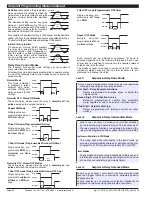
The Tiger 320 Series DI-60A meter can be configured to measure
almost any input signal. The measurement task and sampling rate
for Channel 1 (CH1) is configured in the three digits of Code 2. The
diagram below lists the available configuration selections in Code 2.
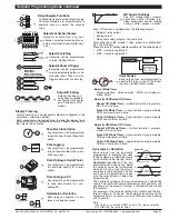
0 Sample Rate: Typically 10 samples/second (60 Hz)
Output Rate: 0.1 seconds
See Example
1 Sample Rate: Typically 10 samples/second (50 Hz)
Output Rate: 0.1 seconds
See Example
2 Sample Rate: Typically 10 samples/second (60 Hz)
Output Rate: 10 millisecs
See Example
3 Sample Rate: Typically 10 samples/second (50 Hz)
Output Rate: 10 millisecs
See Example
Note:
Output Rate refers to setpoint and macro outputs, and input
rates from smart input modules.
Note:
All above sample rates are quoted for single channel opera-
tion. Where more than one channel is available, sample rates
are divided by the number of active channels. See Example.
1 Channel = 10 samples/second
2 Channels = 5 samples/second
3 Channels = 3.33 samples/second
4 Channels = 2.5 samples/second
Example: 10 Samples/Second
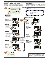
START HERE
Initial Setup Procedures
[CodE_2] - Channel 1 Measurement Task & Sampling Rate
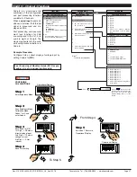
1 =
0.1 second
10 =
1 second
600 =
1 minute
36000 = 1 Hour***
X61 Sets Prescaler
Use
buttons to set
prescale values
P
Press
Use the
buttons to set the
required smart input module code
(0 to 377). See
I-Series Input
Module Guide (Z87)
for code
details.
***Note: For the 1 hour setting,
the scale factor for CH1 must be
set to 0.1 in the calibration mode
setting [111].


