


Texmate, Inc. Tel. (760) 598-9899 • www.texmate.com
Page 28
Apr-21-2016 DI_602A 320 DS (NZ313)_April 2016
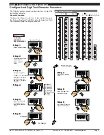
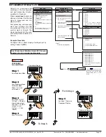
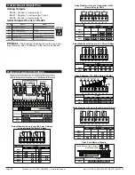
To Step 5
From Step 4
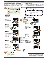
Step 1
Step 2
Step 3
Step 5
Pass Brightness Mode,
Calibration Mode,
Codes 1 to 6, and
enter Code 7
Set Code 6 to [003]
Exit Code 8. Return to
Operational Display
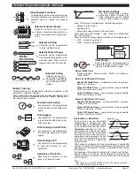
CONFIGURE
1st Digit = 0 Selects
direct display of result
2nd Digit = 0 Selects
no linearization on result
3rd Digit = 3 Selects
result = CH1+CH2
Enter Brightness Mode
RESULT
PROCESSING
SP1
SP3
SP4
SP5
SP6
SP2
F1
P
F2
Operational Display
Press
at same
time
SP1
SP3
SP4
SP5
SP6
SP2
F1
P
F2
Press
8
OR
SP1
SP3
SP4
SP5
SP6
SP2
F1
P
F2
Press
at same
time
SP1
SP3
SP4
SP5
SP6
SP2
F1
P
F2
Operational Display
SP1
SP3
SP4
SP5
SP6
SP2
F1
P
F2
Step 4
Save CH1 & CH2
Result Processing
setting
SP1
SP3
SP4
SP5
SP6
SP2
F1
P
F2
Press
1
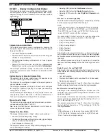
The third digit of Code 7 per-
forms various math functions
between channel 1 and channel
2 and stores this data in the
result register.
The data in the result register
can then be further processed
by the selections made in the
1st and 2nd digits.
Example Procedure:
Configure Code 7 to
add the input of CH1 and CH2 and
directly display the result by setting Code 7 to [
003
].
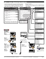
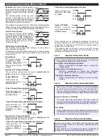
RESULT PROCESSING
0 Direct Display of Result
as per processing per-
formed in 2nd or 3rd digit
1 Square Root of Result
2 Inverse of Result
3 -
32-POINT LINEARIZATION FOR RESULT
0 No Linearization on Result
1 32-point Linearization on Result using Table 1
2 32-point Linearization on Result using Table 2.
See Note 5
3 32-point Linearization on Result using Table 3.
See Note 5
4 32-point Linearization on Result using Table 4.
See Note 5
5 125-point Linearization on Result (Tables 1 to 4 cascaded).
See Note 5
6 32-point Linearization on Result (Tables 1 to 4 selected
from the rear of the meter).
The selected table is not available if CH2, CH3, or CH4 is
operating in the analog mode. CH1 must be set to Voltage,
Current in Code 2 [X0X].
See Note 5
7 –
MATH FUNCTIONS FOR RESULT
0 Result Register not Updated
1 pH Meter (CH1 = Tbuff, CH2 = pH)
2 Result = CH1, Setpoint 2 = CH2
3 Result = CH1 + CH2
4 Result = CH1 - CH2
5 Result = (CH1 x 20 000)/CH2
6 Result = CH1 x CH2/10 000
7 Result = CH1
CODE 7 – RESULT PROCESSING
FIRST DIGIT
SECOND DIGIT
THIRD DIGIT
Linearization Table Notes
A base meter with 4 kB memory installed has a single 32-point program-
mable linearization table available.
For four 32-point programmable linearization tables to be available, the
meter requires at least 32 kB of memory to be installed.
Meters with 4 kB Memory
In base meters with 4 kB memory, set up Table 1 in the Calibration Mode to
[24X]. This means that Table 1 is available to be applied to:
•
CH1 – Selected in Code 3.
•
CH2 – Selected in Code 4.
•
CH3 – Selected in Code 5.
•
CH4 – Selected in Code 6.
Meters with 32 kB Memory
In base meters with 32 kB or more memory, each of the four tables (Tables
1 to 4) are set up in [24X] of the Calibration Mode by selecting the appro-
priate table number. This means that the four tables are available for the
four channels as follows:
•
CH1 – All four tables selected in Code 3.
•
CH2 – All four tables selected in Code 4.
•
CH3 – Table 3 selected in Code 5.
•
CH4 – Table 4 selected in Code 6.
START HERE
Initial Setup Procedures
[CodE_7] - Result Processing
See
I-Series Input Modules Guide (Z87)
for
procedures to set up a dual, triple, or quad
input module.
Note 5:
If only 4 kB memory installed, functions 2
to 6 are not available in:
• Code 3 2nd digit.
• Code 4 3rd digit.
• Code 7 2nd digit.


