


Page 25
Apr-21-2016 DI-602A 320 DS (NZ313)_UL_April 2016
Texmate, Inc. Tel. (760) 598-9899 • www.texmate.com
To Step 4
From Step 3
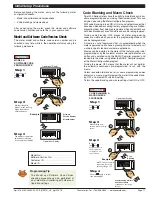
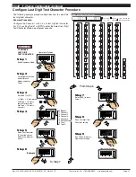
Step 1
Step 2
Step 3
Step 5
Pass Brightness Mode,
Calibration Mode,
Codes 1 to 3, and
enter Code 4
Set Code 4 to [010]
Exit Code 5. Return to
Operational Display
CONFIGURE CH2
1st Digit = 0 Selects
voltage, current
2nd Digit = 1 Selects
direct
3rd Digit = 0 Selects
no linearization
Enter Brightness Mode
MEASUREMENT
TASK
SP1
SP3
SP4
SP5
SP6
SP2
F1
P
F2
Operational Display
Press
at same
time
SP1
SP3
SP4
SP5
SP6
SP2
F1
P
F2
Press
5
OR
SP1
SP3
SP4
SP5
SP6
SP2
F1
P
F2
Press
at same
time
SP1
SP3
SP4
SP5
SP6
SP2
F1
P
F2
Operational Display
SP1
SP3
SP4
SP5
SP6
SP2
F1
P
F2
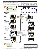
Step 4
Save CH2 Measurement
Task setting
SP1
SP3
SP4
SP5
SP6
SP2
F1
P
F2
Press
1
0 No user defined Linearization
on CH2
1 32-point Linearization on CH2
using Table 1
2 32-point Linearization on CH2
using Table 2.
See Note 5
3 32-point Linearization on CH2
using Table 3.
See Note 5
4 32-point Linearization on CH2
using Table 4.
See Note 5
5 125-point Linearization on CH2
(Tables 1 to 4 cascaded).
See
Note 5
6 –
7 –
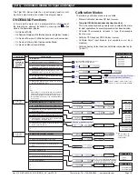
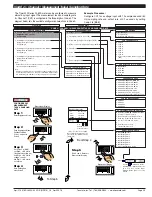
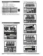
Code 4 is a single code that
combines all the configuration
and post processing functions
available for Channel 2.
When a
dual input
signal con-
ditioner is installed, the second
input signal is processed and
displayed on CH2.
Measurement task and 32-point
linearization for CH2 is config-
ured in the 1st and 2nd digits of
Code 4. The diagram opposite
lists the available configuration
selections in Code 4.
Example Procedure:
Configure CH2 for a voltage input direct with no
linearization
by setting Code 4 to [
010
].
MEASUREMENT TASK
0 Voltage, Current
1 TC (type as per 2nd digit)
2 RTD (type as per 2nd digit)
3 2nd Digital Input Channel (type as
per 2nd digit)
FOR VOLTAGE & CURRENT
0 Channel 2 Disabled
1 Direct (no post processing)
2 Square Root of Channel 2
3 Inverse of Channel 2
4 Output Register 1 (smart module)
5 Output Register 2 (smart module)
6 Output Register 3 (smart module)
7 Output Register 4 (smart module)
32-POINT LINEARIZATION FOR CH2
CODE 4 – CHANNEL 2 MEASUREMENT TASK AND 32-POINT LINEARIZATION
FOR THERMOCOUPLE
0 Type J
1 Type K
2 Type R
3 Type S
4 Type T
5 Type B
6 Type N
7 Select user defined table set up in
CAL [24X]
FOR RTD TYPE (3-WIRE)
0 Resistance
1 RTD 385
2 RTD 392
3 RTD 120
4 Cn10
DIGITAL INPUT
0 Frequency - 99.999 Hz range from 0.01
Hz
1 Frequency - 999.99 Hz range from 0.01 Hz
2 Frequency - 99.999 kHz range from 1 Hz
(1 s gate)
3 Frequency - 500 kHz range from 10 Hz
(0.1 s gate)
4 Period - 9.9999 s (100 µs resolution)
5 Period - 999.99 ms (10 µs resolution)
6 Up/Down Counter with Prescaler
7 Set Prescaler
FIRST DIGIT
SECOND DIGIT
THIRD DIGIT
Use
buttons to set
prescale values from 1 to
65535 counts
Note 5:
If only 4 kB memory installed,
functions 2 to 6 are not avail-
able in:
• Code 3 2nd digit.
• Code 4 3rd digit.
• Code 7 2nd digit.
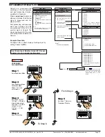
START HERE
Initial Setup Procedures
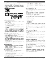
[CodE_4] - Channel 2 Measurement Task & Sampling Rate
See
I-Series Input Modules Guide (Z87)
for pro-
cedures to set up a dual input module.


