


Texmate, Inc. Tel. (760) 598-9899 • www.texmate.com
Page 24
Apr-21-2016 DI_602A 320 DS (NZ313)_April 2016
To Step 4
From Step 3
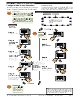
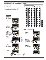
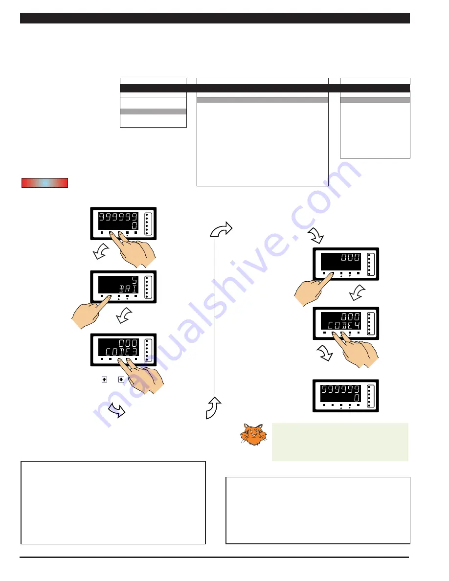
Step 1
Step 2
Step 3
Step 5
Pass Brightness Mode,
Calibration Mode,
Codes 1 and 2, and
enter Code 3
Set Code 3 to [100]
Exit Code 4. Return to
Operational Display
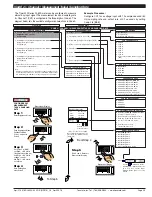
CONFIGURE CH1
1st Digit = 1 Selects
square root of CH1
2nd Digit = 0 Selects
no linearization
3rd Digit = 0 Selects
ASCII Mode
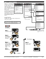
Enter Brightness Mode
POST PROCESSING
FUNCTIONS
SP1
SP3
SP4
SP5
SP6
SP2
F1
P
F2
Operational Display
Press
at same
time
SP1
SP3
SP4
SP5
SP6
SP2
F1
P
F2
Press
4
OR
SP1
SP3
SP4
SP5
SP6
SP2
F1
P
F2
Press
at same
time
SP1
SP3
SP4
SP5
SP6
SP2
F1
P
F2
Operational Display
SP1
SP3
SP4
SP5
SP6
SP2
F1
P
F2
Step 4
Save Post Processing
setting
SP1
SP3
SP4
SP5
SP6
SP2
F1
P
F2
Press
1
Programming tip
For full details on the Serial Mode, see
Serial Communications Output Module
supplement.
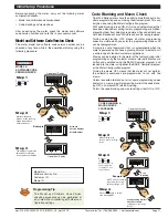
Print Mode – Data Printing Direct to PC
The print mode can also be used to print data to a PC where
it is logged in a Windows Terminal program.
The print mode uses the meter’s serial communications port
to connect to the PC. The data can be logged with or without
a Day: Month: Year or Hours: Minutes: Seconds time stamp.
Time stamp settings are configured in Code 8.
Print Mode – Data Printing Direct to Serial Printer
Print mode data logging is a simple method of capturing data
using the meter’s print mode. The data can be printed directly
to a serial printer from the meter.
The print mode uses the meter’s serial communications port
to connect to a remote serial printer. The data can be printed
with or without a Day: Month: Year or Hours: Minutes: Seconds
time stamp.
Time stamp settings are configured in Code 8.
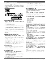
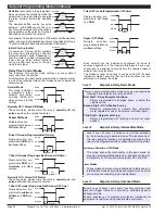
Post processing functions refer to functions that occur to the
input after it has been configured and scaled.
Example Procedure:
Configure the meter to apply square root to the CH1 signal
by
setting Code 3 to [
100
].
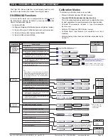
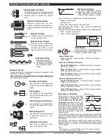
FIRST DIGIT
SECOND DIGIT
THIRD DIGIT
CH1 POST PROCESSING
0 Direct Display of Input (no
processing)
1 Square Root of Channel 1
2 Inverse of Channel 1
3 –
32-POINT LINEARIZATION FOR CHANNEL 1
0 No Linearization on CH1
1 32-point Linearization on CH1 using Table 1
2 32-point Linearization on CH1 using Table 2.
See Note 5
3 32-point Linearization on CH1 using Table 3.
See Note 5
4 32-point Linearization on CH1 using Table 4.
See Note 5
5 125-point Linearization on CH1 (Tables 1 to 4 cascaded).
See
Note 5
6 32-point Linearization on CH1 (Tables 1 to 4 selected from the
rear pins of selected input modules).
The selected table is not available if CH2, CH3, or CH4 is oper-
ating in the analog output mode. CH1 must be set to Voltage,
Current in Code 2 [X0X].
See Note 5
7 -
Note:
All linearization tables are set up in the Calibration Mode [24X].
SERIAL MODE
0 ASCII Mode
1 Modbus Mode
2 Master mode (used to cus-
tomize print mode protocols
via macro)
3 Print Mode
4 Ethernet Mode.
See Note 6
5 Devicenet Mode (no longer
supported).
CODE 3 – CHANNEL 1 FUNCTIONS (POST PROCESSING & SERIAL MODE)
Post processing for Channel
1 (CH1) is configured in the
first digit of Code 3. The dia-
gram below lists the available
post processing configuration
selections in Code 3 (1st digit
only).
Note 6:
These functions are not available
on all models and in some cases
require additional hardware.
Note 5:
If only 4 kB memory installed, functions 2
to 6 are not available in:
• Code 3 2nd digit.
• Code 4 3rd digit.
• Code 7 2nd digit.
START HERE
Initial Setup Procedures
[CodE_3] - Channel 1 Post Processing & Serial Mode Functions


