


Texmate, Inc. Tel. (760) 598-9899 • www.texmate.com
Page 32
Apr-21-2016 DI_602A 320 DS (NZ313)_April 2016
Setpoint Programming Mode continued
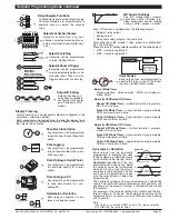
Initial Start-up Inhibit.
On power-on, start-up inhibit prevents
the relay from energizing on the first
setpoint activation cycle. Depending on
how the meter has been programmed,
initial start-up inhibit either functions
during a falling input signal, or during a
rising input signal.
Relay Time Control Modes
The following time control mode settings can cover almost
every relay timer application.
All setpoints can be individually programmed to operate a relay
in one of the following time control modes above or below the
setpoint value.
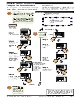
Normal Mode
This mode individual-
ly programs a relay’s
setpoint with delay-
on-make (DOM) and
delay-on-break (DOB)
settings.
SP ON
SP OFF
Normal Mode
Adj.
DOM
Adj.
DOB
RLY ON
RLY OFF
Normally OFF / Pulsed ON Modes
These are delay modes were the relay is
normally off
and
pulses on
when the setpoint activates.
Repeat ON Mode
Multiple actuation,
programmable
on
and
off time
settings.
Repeat ON Mode
SP ON
SP OFF
Adj.
ON-T
Adj.
OFF-T
RLY ON
RLY OFF
Adj.
ON-T
Pulse ON mode (Programmable ON-time)
Single actuation, pro-
grammable
DOM
and
on time
settings.
SP ON
SP OFF
Pulse ON Mode (Prog. Max ON-time)
Adj.
MAX
ON-T
RLY ON
RLY OFF
Adj.
DOM
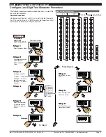
Deviation
(passband) is the programma-
ble band around the setpoint in which the
setpoint can be programmed to energize
the relay inside or outside the deviation
band.
The deviation setting can be any value
between 1 and 65535 counts. The num-
ber of counts selected act both positively
and negatively on the setpoint, forming a
deviation band around the setpoint.
For example, if the setpoint setting is 1000 counts and the deviation
setting is 35 counts, the deviation band around the setpoint setting is
70 counts starting at 965 counts and ending at 1035 counts.
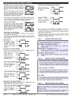
SP
Deviation
Band
SP
Deviation
Band
Energized Inside
Energized Outside
Deviation
+
–
+
–
SP
Hysteresis
Band
SP
Hysteresis
Band
Energized Below
Energized Above
Hytseresis
+
–
+
–
1-Shot ON mode (Programmable Minimum ON-time)
Single actuation, pro-
grammable
DOM
and
minimum on time
settings.
SP ON
SP OFF
1-Shot ON Mode (Prog. Min. ON-time)
Adj.
MIN ON-T
RLY ON
RLY OFF
Adj.
DOM
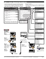
Normally ON / Pulsed OFF Modes
These are delay modes were the relay is
normally on
and
pulses off
when the setpoint activates.
1-Shot OFF mode (Programmable Minimum OFF-time)
SP OFF
SP ON
1-Shot OFF Mode (Prog. Min. OFF-time)
Adj.
MIN OFF-T
RLY ON
RLY OFF
Adj.
DOB
Single actuation, pro-
grammable
minimum
off time
and
DOB
set-
tings.
Pulse OFF mode (Programmable OFF-time)
Repeat OFF Mode
Multiple actuation,
programmable
off
and
on time
settings.
SP OFF`
SP ON
Repeat OFF Mode
Adj.
OFF-T
Adj.
ON-T
RLY ON
RLY OFF
Adj.
OFF-T
Single actuation, pro-
grammable
off time
and
DOB
.
SP OFF
SP ON
Pulse OFF Mode (Prog. MAX OFF-time)
Adj.
MAX
OFF-T
RLY ON
RLY OFF
Adj.
DOB
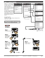
Setpoint & Relay Basic Mode
Level 1
This is an easily programmable mode for users who require the
following basic setpoint and relay functions:
First Digit – Relay Energize Functions
Relays programmed to energize above or below the
setpoint value.
Second Digit – SP Activation Source
Setpoints programmed to activate from selectable
meter registers or one of six external switched inputs.
Third Digit – Setpoint Latching
Relays programmed with latching and manual reset
options.
Each setpoint can be individually configured for basic to
advanced operations in the following three levels. Each oper-
ational level is designed to provide only the required relevant
setpoint and relay functions.
The modes at Level 2 and Level 3 can be set to OFF for each
individual setpoint, ensuring that no other functions are pro-
grammed to influence the setup.
Setpoint & Relay Intermediate Mode
This mode adds extra functionality to the basic mode by
providing programmable hysteresis or deviation settings for
all setpoints, or PID control from setpoints SP1 and SP2.
These modes add even more functionality to the basic and
intermediate mode by providing each setpoint with a choice
of one of seven resident programmable timers.
Level 2
Timer Modes
Hysteresis, Deviation & PID Mode
Level 2 uses all Level 1 functions and is further extended
by the following programmable modes. The functionality of
the relay energize functions are extended by allowing the
relays to be programmed with or without initial start-up inhibit.
Level 3 uses all Level 1 and Level 2 functions combined with
reset and trigger functions to provide an extremely powerful
advanced mode.
Level 3 enables you to program all setpoints individually for
operations normally requiring sophisticated controllers.
Level 3
Setpoint & Relay Advanced Mode


