


Texmate, Inc. Tel. (760) 598-9899 • www.texmate.com
Page 14
Apr-21-2016 DI_602A 320 DS (NZ313)_April 2016
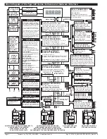
[CAL] - Calibration Modes for Input and Output continued
[CAL] - Calibration Modes for Input and Output continued
Related Calibration Functions
The following functions are also configured in the calibration
mode. See
Advanced Calibration and On Demand Mode
Supplement (NZ203)
for further calibration details.
Serial Communications Properties
Selecting [CAL][20X] enters the Serial Communications
Properties Mode.
This mode allows you to configure the serial communications
output module baud rate, parity, time delay, and address set-
tings.
See the
calibration modes
diagram on Page 13 showing a
breakdown of 1st, 2nd, and 3rd digits.
Also see the Serial Communications Module Supplement
(NZ202) for further details on the serial communications module.
Set Auto Zero Maintenance
Selecting [CAL][21X] enters the Set Auto Zero Maintenance
Mode.
This mode allows you to configure auto zero maintenance set-
tings for weighing applications applied to the channel selected
in the 3rd digit.
See the
calibration modes
diagram on Page 13 showing a
breakdown of 1st, 2nd, and 3rd digits.
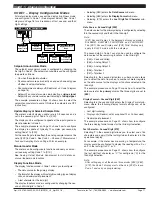
Set Averaging Samples & Averaging Window
Selecting [CAL][22X] enters the Set Averaging Samples and
Averaging Windows Mode.
This mode allows you to configure the number of input signal
samples to average over, and the size of the averaging window
in display counts applied to the channel selected in the 3rd digit.
Selecting [CAL][22X] enters the Set Averaging Samples and
Averaging Windows Mode. When in this mode, the [AV_S]
menu allows you to select the number of input signal samples
to average over. After setting the number of samples, moving
to the [AV_W] menu allows you to configure the size of the
averaging window in displayed counts.
The meter averages the input samples over the selected num-
ber of input samples (selected in the [AV_S] menu). This carries
on in a continual process provided the input signal stays within
the averaging window (set in the [AV_W] menu). If the sample
moves out of the averaging window, the meter responds quick-
ly to the change by displaying the non-averaged signal value.
When the signal stabilizes, a new averaging window is estab-
lished and averaging resumes.
You can program the number of samples you want to average
the input signal over from 1 to 255 samples. The averaging
window can be set to between 1 and 65535 counts.
See the
calibration modes
diagram on Page 13 showing a
breakdown of 1st, 2nd, and 3rd digits.
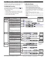
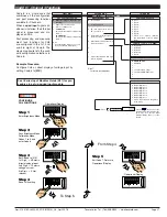
See Input Signal Sampling Showing Averaging Window dia-
gram opposite.
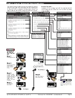
Example Procedure
The example procedure on Page 16 shows how to configure
channel 1 (CH1) with an averaging sample rate of 10 counts
and an averaging window of 1000 counts.
Totalizer Settings
Selecting [CAL][23X] enters the Totalizer Settings Mode.
This mode allows you to configure the settings for the totalizer
selected in the 3rd digit. An input value of 10000 counts is
applied to a selectable time period to produce the required
total value.
The cutoff is a programmable limit below which the input is not
totalized.
See the
calibration modes
diagram on Page 13 showing a
breakdown of 1st, 2nd, and 3rd digits.
Also see the Totalizing and Batching Supplement (NZ208) for
further details on K factor and totalizer cutoff parameters.
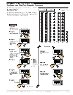
Setup 32-point Linearization Tables
Selecting [CAL][24X] enters the Setup 32-point Linearization
Tables Mode.
This mode allows you to set up the linearization table or tables
using the manual or auto setup modes. The table or tables can
then be selected to linearize the signals on channels 1 to 4.
See
Linearization Table Notes
on Page 28 for a description of
memory related issues with linearization.
See the
calibration modes
diagram on Page 13 showing a
breakdown of 1st, 2nd, and 3rd digits.
Also see the Linearizing Supplement (NZ207) for further details
on linearization table setup and use.
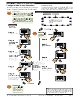
Scale Analog Output
Selecting [CAL][25X] enters the Scale Analog Output Mode.
This mode allows you to calibrate and scale the analog output
signal. Before calibrating the analog output in the calibration
mode, the data source for the analog output must be configured
in Code 1.
See the
calibration modes
diagram on Page 13 showing a
breakdown of 1st, 2nd, and 3rd digits.
Also see the Analog Output Module Supplement (NZ200) for
further details on the analog output module.
Also see Configure Data Source Procedure on Page 19 for an
example of setting the analog output data source.
Calibration Mode Procedures Supplement
The
Advanced
Calibration and On Demand Mode Procedures
Supplement
(NZ203) describes in detail all Tiger 320 Series
meter related calibration procedures configured in the calibra-
tion mode.
Sampling
Input Signal in Counts
= Samples
= Averaging Window
Averaging Window
in Displayed Counts
Number of
Samples
Input Signal Sampling Showing Averaging Window


