


Chapter 6
Advanced Topics
109
Figure 6-20: Functional Block Diagram: CCD Array
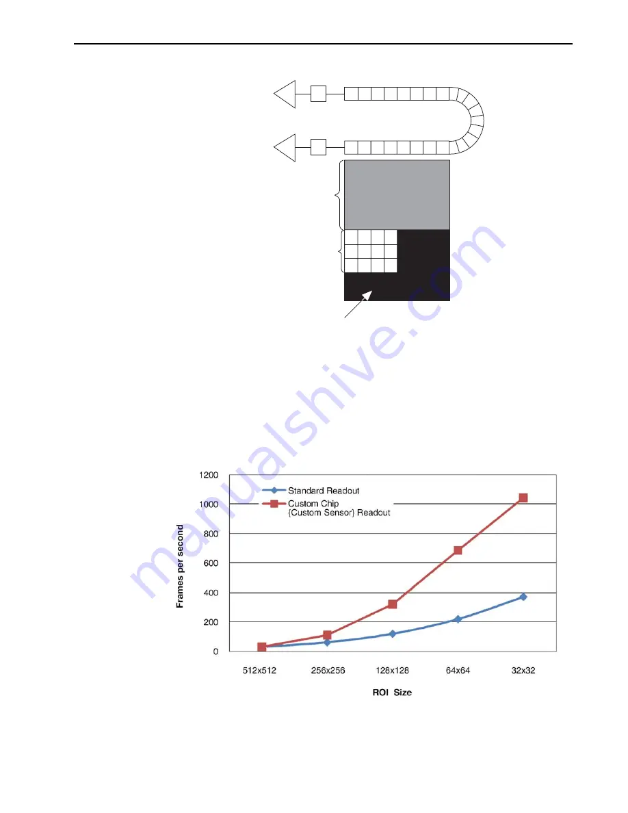
The following example compares the time savings achieved by using Custom Chip
{Custom Sensor} vs. ROI to read out a 128 x 128 region of a 512 x 512 array.
Using the ROI method to read out the 128 x 128 pixels would take 8.2 ms, or a frame
rate of 122 fps (1/0.0082). Using the Custom Chip {Custom Sensor} feature, the readout
time for the same region would drop to 3.1 ms (equivalent to a frame rate of 323 fps).
See
for a graphic comparison of the ProEM:512B camera's expected frame
rates using standard ROI readout and custom chip readout.
Figure 6-21: Comparison of Standard ROI and Custom Chip Readout Rates
External (custom)
mask for “Custom
chip” readout
Frame-transfer
Area
Active Area
441
1-
0
12
6
_
0
0
6
5
4
4
11
-01
26
_
006
6
Summary of Contents for ProEM Series
Page 1: ...www princetoninstruments com ProEM System Manual 4411 0126 Issue 3 September 26 2019 ...
Page 10: ...10 ProEM System Manual Issue 3 This page is intentionally blank ...
Page 16: ...16 ProEM System Manual Issue 3 This page is intentionally blank ...
Page 30: ...30 ProEM System Manual Issue 3 This page is intentionally blank ...
Page 50: ...50 ProEM System Manual Issue 3 This page is intentionally blank ...
Page 88: ...88 ProEM System Manual Issue 3 This page is intentionally blank ...
Page 114: ...114 ProEM System Manual Issue 3 This page is intentionally blank ...
Page 122: ...122 ProEM System Manual Issue 3 Figure 7 8 LightField Settings 4411 0126_0078 ...
Page 136: ...136 ProEM System Manual Issue 3 This page is intentionally blank ...
Page 146: ...146 ProEM System Manual Issue 3 This page is intentionally blank ...
Page 152: ...152 ProEM System Manual Issue 3 This page is intentionally blank ...
Page 161: ...This page is intentionally blank ...


