Functional Check
WFM 601i Serial Component Monitor
1–19
.7
.6
.8
.5
.4
.3
.2
.1
–.1
–.2
–.3
Tek
COMPONENT ANALOG
2% & 4% K
PB
100%
50%
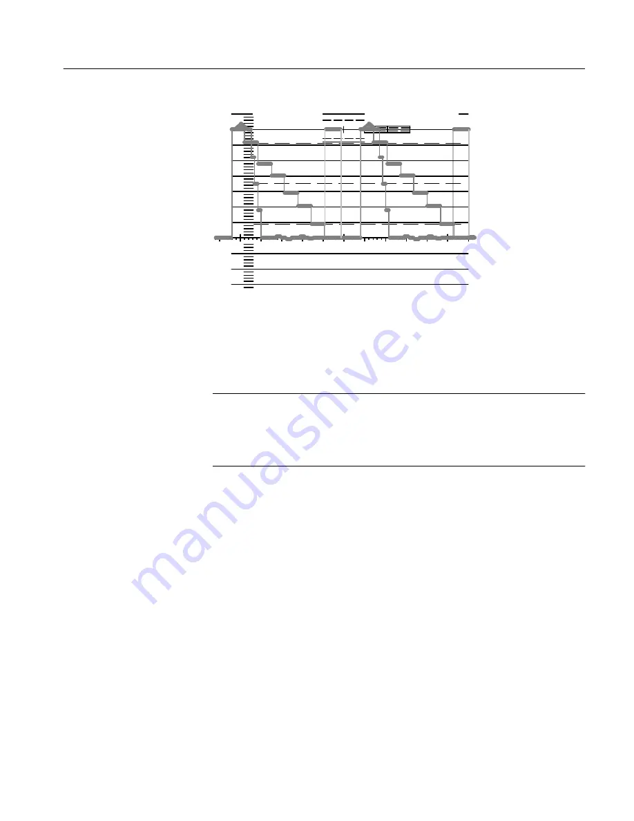
Figure 1-12: Channel 1 of color bar with level reference on the WFM 601i.
Press the top front-panel bezel button to select READOUT. One of the knobs
now controls the readout intensity. Adjust the control to the desired level.
NOTE
. READOUT INTENSITY controls the intensity of the menus that are used
to select and setup instrument operation. Be sure to set this level at a
comfortable, yet visible setting. If the readout intensity is accidently turned too
low to see, consult the CRT Menu discussion on page 2–21 for the recovery
procedure.
Press the top bezel button again to select TRACE. One of the knobs now
controls the trace rotation. Adjust the control for a level signal baseline parallel
to the graticule 0 line.
Press the bottom bezel button to turn on RO TEST. Note that a cross mark is
now displayed at the center of the 0.7 volt line, directly under the target mark.
Exit the CRT menu by pressing either the CLEAR MENU or the CRT button.
The changes made while the menu was displayed remain in effect, but the
readout test mark disappears.
Summary of Contents for WFM 601i
Page 4: ......
Page 12: ...Contents vi WFM 601i Serial Component Monitor...
Page 16: ...Preface x WFM 601i Serial Component Monitor...
Page 17: ...Getting Started...
Page 18: ......
Page 51: ...Operating Basics...
Page 52: ......
Page 58: ...At A Glance 2 6 WFM 601i Serial Component Monitor...
Page 76: ...Functional Overview 2 24 WFM 601i Serial Component Monitor...
Page 77: ...Reference...
Page 78: ......
Page 104: ...Measurement Theory 3 26 WFM 601i Serial Component Monitor...
Page 105: ...Appendices...
Page 106: ......
Page 118: ...Appendix B Multipin Connectors B 4 WFM601i Serial Component Monitor...
Page 123: ...Glossary...
Page 124: ......
Page 129: ...Index...
Page 130: ......
Page 134: ......
Page 135: ......


