1730–Series Operating Instructions
2–26
REV MAY 1993
120
100
80
60
40
20
–20
–40
1.2
1.0
1.1
0.9
0.8
0.7
0.6
0.5
0.4
0.2
0.1
0
PAL
NTSC
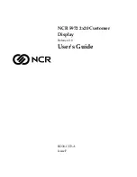
Figure 2-18: Dual standard graticule.
Preset Front-Panel Measurements
The 1730–Series has four front–panel setups stored in internal memory. A TTL
low (or ground closure) on one of the PRESET enables (pins 12 through 15 of
the REMOTE connector) selects one of these pre–programmed, front–panel
setups. Table 2–1 shows the preset front panels that are stored in memory.
When the 1730–Series is used as a direct replacement for the TEKTRONIX
528A Waveform Monitor (which used dc voltage levels as enables), it will be
necessary to use a conversion circuit to change these positive voltage levels to
apparent ground closures. See Figure 3-3 for a simple conversion circuit.
Table 2–1: Preset Front Panels
Front–Panel Control
Preset 1
(pin 13)
Preset 2
(pin 14)
Preset 3
(pin 15)
Preset 4
(pin 12)
INPUT Channel
A
A
A
A
INPUT Reference
EXT
INT
INT
INT
INPUT Filter
FLAT
FLAT
FLAT
FLAT
VERTICAL Gain (VAR)
off
off
off
off
VERTICAL Gain (X5)
off
off
off
off
VERTICAL DC Restorer
OFF
OFF
SLOW
SLOW
HORIZONTAL Field
FLD 1
ALL
ALL
FLD 1
HORIZONTAL Sweep
2 FLD
2 LINE
1 LINE
2 LINE
Summary of Contents for 1730 Series
Page 4: ......
Page 12: ...Contents viii...
Page 17: ...Introduction and Specifications...
Page 18: ......
Page 32: ...1730 Series Introduction 1 14...
Page 33: ...Operating Instructions...
Page 34: ......
Page 62: ...1730 Series Operating Instructions 2 28...
Page 64: ...Service Safety Summary S 2 1730 Series B070000 Above...
Page 66: ......
Page 67: ...Installation...
Page 68: ......
Page 82: ...1730 Series Installation 3 14...
Page 83: ...Theory of Operation...
Page 84: ......
Page 115: ...Checks and Adjustments...
Page 116: ......
Page 159: ...Maintenance...
Page 160: ......
Page 180: ...1730 Series Maintenance 6 20 3 Remove the board by slipping it through the front panel opening...
Page 184: ...1730 Series Maintenance 6 24 Figure 6 8 Repackaging a 1730 Series instrument...
Page 185: ...Options...
Page 186: ......
Page 189: ...Replaceable Electrical Parts...
Page 190: ......
Page 222: ...1730 Series Replaceable Electrical Parts 8 32...
Page 223: ...Diagrams Circuit Board Illustrations...
Page 224: ......
Page 246: ......
Page 247: ...Replaceable Mechanical Parts...
Page 248: ......
Page 255: ...1730 Series Waveform Monitor FIG 1 EXPLODED VIEW A1 A3 A2 A3A1 A10 A11...
Page 256: ...1730 Series B070000 Up...
Page 257: ......
Page 258: ......