


8 - 2
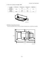
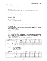
Chapter 8 Printer Specifications
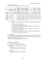
2. Electrical Properties
2.1 Power Source
Two types of power source as follows are available for this printer, which are selected according to the
specifications.
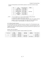
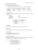
2.1.1 For 120 VAC Printer
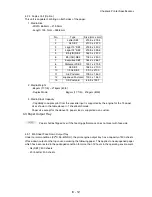
2.1.2 For 220/240 VAC Printer
2.2 Power Consumption
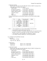
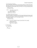
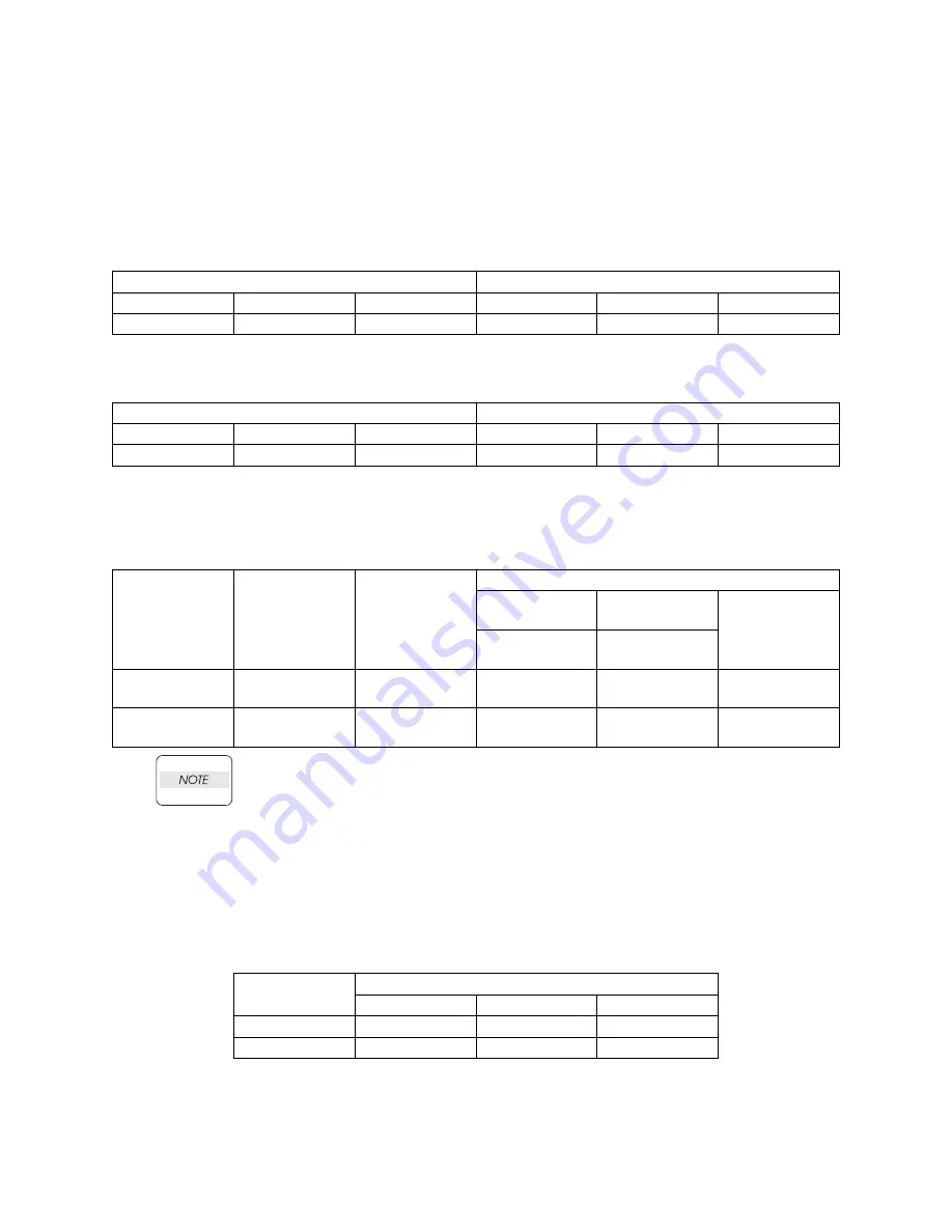
2.2.1 Maximum Power Consumption
:
1. No electrical current shall be supplied to the Fuser unit in Low Power Mode.
2. No electrical current shall be supplied to the Fuser / Fan / MCU unit in Sleep Mode.
3. Power consumption is without the Controller.
4. Specified with FX method.
5. The controller consuming current at low power mode 2 and sleep mode shall not
exceed 1A @ 3.3V and 0.5A @ 5V.
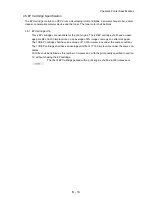
2.2.2 Average Power Consumption
Voltage
Frequency
Min
Nominal
Max
Min
Nominal
Max
98VAC
120VAC
132VAC
47Hz
50/60Hz
63Hz
Voltage
Frequency
Min
Nominal
Max
Min
Nominal
Max
198VAC
220/240VAC
264VAC
47Hz
50/60Hz
63Hz
Operation
(+/- 10%)
Power
Consumption
Electrical
Current
Power Consumption
Low Power
Mode 1
Low Power
Mode 2
Sleep Mode
*5
(Fan Stop)
Fan Low
Speed
Fan Stop
*5
110 VAC
Maximum:
1210 W
Maximum:
12.2 A
Maximum:
16.5 W
Maximum:
6.5 W
Maximum:
3.5 W
220 VAC
Maximum:
1270 W
Maximum:
5.8 A
Maximum:
17.6 W
Maximum:
9.0 W
Maximum:
5.0 W
Input
Voltage
Base w/OCT and Option Feeder
Standby
Simplex
Duplex
120 VAC
110 W
880 W
629 W
230 VAC
89 W
728 W
633 W
Summary of Contents for 9045N
Page 1: ...Laser Printer TallyGenicom 9045N Service Manual J20006AA ...
Page 16: ...xv Blank Page ...
Page 20: ...Chapter 1 Troubleshooting Chapter 1 Troubleshooting CONTENTS Blank Page ...
Page 88: ...1 68 Chapter 1 Troubleshooting Blank Page ...
Page 160: ...1 140 Chapter 1 Troubleshooting Blank Page ...
Page 162: ...1 142 Chapter 1 Troubleshooting Blank Page ...
Page 164: ...Chapter 2 Printer Diagnostics Chapter 2 Diagnostics CONTENTS 11 Print Summary 2 16 ...
Page 194: ...1 10 Chapter 3 Removal and Replacement Procedures RRPs RRP2 150 PAPER CASSETTE ...
Page 213: ...1 29 Chapter 3 Removal and Replacement Procedures RRPs RRP3 550 PAPER CASSETTE ...
Page 240: ...1 56 Chapter 3 Removal and Replacement Procedures RRPs RRP4 150 paper Feeder ...
Page 257: ...1 73 Chapter 3 Removal and Replacement Procedures RRPs RRP5 550 Paper Feeder ...
Page 277: ...1 93 Chapter 3 Removal and Replacement Procedures RRPs RRP6 Xerographics ...
Page 302: ...1 118 Chapter 3 Removal and Replacement Procedures RRPs RRP7 500 Paper Exit ...
Page 322: ...1 138 Chapter 3 Removal and Replacement Procedures RRPs RRP8 Frame Drive ...
Page 331: ...1 147 Chapter 3 Removal and Replacement Procedures RRPs RRP9 Electrical ...
Page 394: ...1 210 Chapter 3 Removal and Replacement Procedures RRPs ...
Page 454: ...1 270 Chapter 3 Removal and Replacement Procedures RRPs Blank Page ...
Page 459: ...4 3 Chapter 4 Plug Jack P J Connector Locations Blank Page ...
Page 465: ...4 9 Chapter 4 Plug Jack P J Connector Locations 3 2 OCT Option P J Diagram ...
Page 468: ...4 12 Chapter 4 Plug Jack P J Connector Locations Blank Page ...
Page 470: ...Chapter 5 Parts Lists Chapter 5 Parts Lists CONTENTS Blank Page ...
Page 479: ...5 9 Chapter 5 Parts List Blank Page ...
Page 483: ...5 13 Chapter 5 Parts List Blank Page ...
Page 490: ...5 20 Chapter 5 Parts List PL 7 2 500 PAPER EXIT 2 2 OPTION FACE UP TRAY ILLUSTRA TION ...
Page 496: ...5 26 Chapter 5 Parts List OPTIONS PL 10 1 OPTION DUPLEX ILLUSTRATION ...
Page 501: ...5 31 Chapter 5 Parts List Blank Page ...
Page 529: ...6 19 Chapter 6 Principles of Operation J26119AA EP CARTRIDGE BTR ASSY ...
Page 531: ...6 21 Chapter 6 Principles of Operation LD Assembly JG6121AA SOS PWB Scanner Assembly ...
Page 535: ...6 25 Chapter 6 Principles of Operation ...
Page 558: ...6 48 Chapter 6 Principles of Operation Blank Page ...
Page 584: ...7 24 Chapter 7 Wiring Diagrams and Signal Information Blank Page ...
Page 608: ...Chapter 9 ESS Options Chapter 9 Controller ESS Options Contents Blank Page ...


