

6 – 27
Chapter 6 Principles of Operation
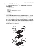
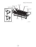
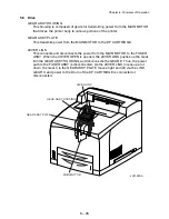
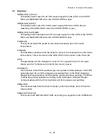
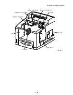
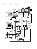
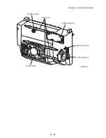
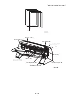
5.7 Electrical
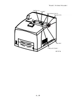
INTERLOCK S/W 24V
This safety switch cuts off a 24 VDC power supply from the LVPS to the HVPS
MCU and MAIN MOTOR when the COVER OPEN is open.
INTERLOCK S/W 5V
This safety switch cuts off a 5 VDC power supply from the LVPS to the LD
Assembly of the ROS ASSY when the COVER OPEN is open.
INTERLOCK S/W REAR
This safety switch interrupts a 24 VDC power supply from the LVPS to the HVPS/
MCU and MAIN MOTOR when the COVER REAR is open.
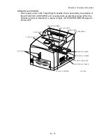
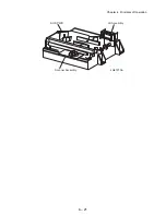
FAN MAIN
This vents air inside the printer to prevent an excessive rise in the inside
temperature.
FAN SUB
This fan takes outside air into the printer to prevent an excessive rise in the inside
temperature. This is mounted on the ROS ASSY in the center on the front side.
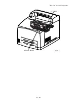
LVPS
This generates low DC voltages (5 V and 3 V for Logical Circuit, 5 V for Laser
Diode, and 24 V for Motor and Clutch) from the AC power.
HVPS/MCU
The functions of the HVPS and MCU are incorporated in this substrate. The HVPS
generates high AC and DC voltages and supplies them to the BCR (charging),
Magnet Roll (development), BTR (transfer), and Detack Saw (peeling). The MCU
controls the printing operation according to the information obtained through
communications with the Print Controller and from sensors and switches.
PWBA ESS
This receives data from the Host Computer, performs printing, and controls the
whole printer.
PWBA EXIT MOTOR
This controls the MOTOR ASSY EXIT according to a signal from the HVPS/MCU.
Summary of Contents for 9045N
Page 1: ...Laser Printer TallyGenicom 9045N Service Manual J20006AA ...
Page 16: ...xv Blank Page ...
Page 20: ...Chapter 1 Troubleshooting Chapter 1 Troubleshooting CONTENTS Blank Page ...
Page 88: ...1 68 Chapter 1 Troubleshooting Blank Page ...
Page 160: ...1 140 Chapter 1 Troubleshooting Blank Page ...
Page 162: ...1 142 Chapter 1 Troubleshooting Blank Page ...
Page 164: ...Chapter 2 Printer Diagnostics Chapter 2 Diagnostics CONTENTS 11 Print Summary 2 16 ...
Page 194: ...1 10 Chapter 3 Removal and Replacement Procedures RRPs RRP2 150 PAPER CASSETTE ...
Page 213: ...1 29 Chapter 3 Removal and Replacement Procedures RRPs RRP3 550 PAPER CASSETTE ...
Page 240: ...1 56 Chapter 3 Removal and Replacement Procedures RRPs RRP4 150 paper Feeder ...
Page 257: ...1 73 Chapter 3 Removal and Replacement Procedures RRPs RRP5 550 Paper Feeder ...
Page 277: ...1 93 Chapter 3 Removal and Replacement Procedures RRPs RRP6 Xerographics ...
Page 302: ...1 118 Chapter 3 Removal and Replacement Procedures RRPs RRP7 500 Paper Exit ...
Page 322: ...1 138 Chapter 3 Removal and Replacement Procedures RRPs RRP8 Frame Drive ...
Page 331: ...1 147 Chapter 3 Removal and Replacement Procedures RRPs RRP9 Electrical ...
Page 394: ...1 210 Chapter 3 Removal and Replacement Procedures RRPs ...
Page 454: ...1 270 Chapter 3 Removal and Replacement Procedures RRPs Blank Page ...
Page 459: ...4 3 Chapter 4 Plug Jack P J Connector Locations Blank Page ...
Page 465: ...4 9 Chapter 4 Plug Jack P J Connector Locations 3 2 OCT Option P J Diagram ...
Page 468: ...4 12 Chapter 4 Plug Jack P J Connector Locations Blank Page ...
Page 470: ...Chapter 5 Parts Lists Chapter 5 Parts Lists CONTENTS Blank Page ...
Page 479: ...5 9 Chapter 5 Parts List Blank Page ...
Page 483: ...5 13 Chapter 5 Parts List Blank Page ...
Page 490: ...5 20 Chapter 5 Parts List PL 7 2 500 PAPER EXIT 2 2 OPTION FACE UP TRAY ILLUSTRA TION ...
Page 496: ...5 26 Chapter 5 Parts List OPTIONS PL 10 1 OPTION DUPLEX ILLUSTRATION ...
Page 501: ...5 31 Chapter 5 Parts List Blank Page ...
Page 529: ...6 19 Chapter 6 Principles of Operation J26119AA EP CARTRIDGE BTR ASSY ...
Page 531: ...6 21 Chapter 6 Principles of Operation LD Assembly JG6121AA SOS PWB Scanner Assembly ...
Page 535: ...6 25 Chapter 6 Principles of Operation ...
Page 558: ...6 48 Chapter 6 Principles of Operation Blank Page ...
Page 584: ...7 24 Chapter 7 Wiring Diagrams and Signal Information Blank Page ...
Page 608: ...Chapter 9 ESS Options Chapter 9 Controller ESS Options Contents Blank Page ...


