


2 - 7
Chapter 2 Diagnostics
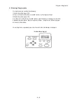
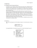
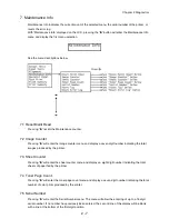
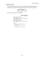
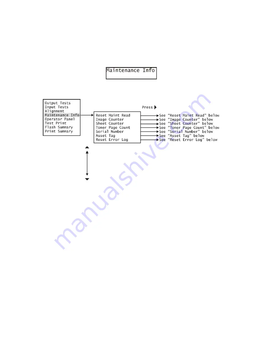
7. Maintenance Info
Maintenance Info indicates the current count of the selected menu, the serial number of the printer, or
resets the error log.
With “Maintenance Info” displayed on the LCD, pressing the “
X
” button will enter the Maintenance Info
menu and display the first menu selection.
See the menu descriptions below.
7.1 Reset Maint Read
Pressing “
X
” resets the Maintenance counter.
7.2 Image Counter
Pressing “
X
” will enter the image counter menu and display a seven digit number indicating the total
images produced by the printer.
7.3 Sheet Counter
Pressing “
X
” will enter the sheet counter menu and display an eight digit number indicating the total
sheets of paper fed by the printer.
7.4 Toner Page Count
Pressing “
X
” will enter the toner page count menu and display a seven digit number indicating the total
number of color prints produced by the printer.
7.5 Serial Number
Pressing “
X
” will enter the Serial Number menu. The menu will allow the entering of up to a 16 digit
serial number. If no number has previously been entered, the second line of the display will be blank
with a line at the bottom of the first digit position.
Summary of Contents for 9045N
Page 1: ...Laser Printer TallyGenicom 9045N Service Manual J20006AA ...
Page 16: ...xv Blank Page ...
Page 20: ...Chapter 1 Troubleshooting Chapter 1 Troubleshooting CONTENTS Blank Page ...
Page 88: ...1 68 Chapter 1 Troubleshooting Blank Page ...
Page 160: ...1 140 Chapter 1 Troubleshooting Blank Page ...
Page 162: ...1 142 Chapter 1 Troubleshooting Blank Page ...
Page 164: ...Chapter 2 Printer Diagnostics Chapter 2 Diagnostics CONTENTS 11 Print Summary 2 16 ...
Page 194: ...1 10 Chapter 3 Removal and Replacement Procedures RRPs RRP2 150 PAPER CASSETTE ...
Page 213: ...1 29 Chapter 3 Removal and Replacement Procedures RRPs RRP3 550 PAPER CASSETTE ...
Page 240: ...1 56 Chapter 3 Removal and Replacement Procedures RRPs RRP4 150 paper Feeder ...
Page 257: ...1 73 Chapter 3 Removal and Replacement Procedures RRPs RRP5 550 Paper Feeder ...
Page 277: ...1 93 Chapter 3 Removal and Replacement Procedures RRPs RRP6 Xerographics ...
Page 302: ...1 118 Chapter 3 Removal and Replacement Procedures RRPs RRP7 500 Paper Exit ...
Page 322: ...1 138 Chapter 3 Removal and Replacement Procedures RRPs RRP8 Frame Drive ...
Page 331: ...1 147 Chapter 3 Removal and Replacement Procedures RRPs RRP9 Electrical ...
Page 394: ...1 210 Chapter 3 Removal and Replacement Procedures RRPs ...
Page 454: ...1 270 Chapter 3 Removal and Replacement Procedures RRPs Blank Page ...
Page 459: ...4 3 Chapter 4 Plug Jack P J Connector Locations Blank Page ...
Page 465: ...4 9 Chapter 4 Plug Jack P J Connector Locations 3 2 OCT Option P J Diagram ...
Page 468: ...4 12 Chapter 4 Plug Jack P J Connector Locations Blank Page ...
Page 470: ...Chapter 5 Parts Lists Chapter 5 Parts Lists CONTENTS Blank Page ...
Page 479: ...5 9 Chapter 5 Parts List Blank Page ...
Page 483: ...5 13 Chapter 5 Parts List Blank Page ...
Page 490: ...5 20 Chapter 5 Parts List PL 7 2 500 PAPER EXIT 2 2 OPTION FACE UP TRAY ILLUSTRA TION ...
Page 496: ...5 26 Chapter 5 Parts List OPTIONS PL 10 1 OPTION DUPLEX ILLUSTRATION ...
Page 501: ...5 31 Chapter 5 Parts List Blank Page ...
Page 529: ...6 19 Chapter 6 Principles of Operation J26119AA EP CARTRIDGE BTR ASSY ...
Page 531: ...6 21 Chapter 6 Principles of Operation LD Assembly JG6121AA SOS PWB Scanner Assembly ...
Page 535: ...6 25 Chapter 6 Principles of Operation ...
Page 558: ...6 48 Chapter 6 Principles of Operation Blank Page ...
Page 584: ...7 24 Chapter 7 Wiring Diagrams and Signal Information Blank Page ...
Page 608: ...Chapter 9 ESS Options Chapter 9 Controller ESS Options Contents Blank Page ...


