


6 – 14
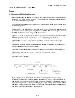
Chapter 6 Principles of Operation
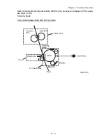
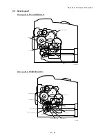
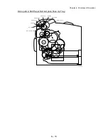
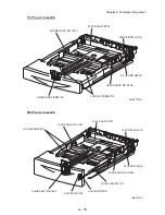
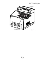
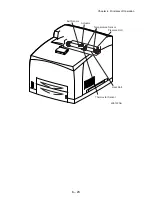
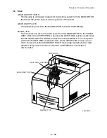
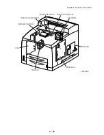
GUIDE ASSY L150 and GUIDE ASSY SD R150
The GUIDE ASSY SD R150 can be adjusted to different paper sizes by moving it
to the left or right. The guides come into contact with the left and right edges of the
paper and hold it in position. The GUIDE ASSY SD L150 moves simultaneously
with the GUIDE ASSY SD R150.
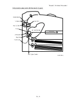
LOCK EXTENSION
The 150 Paper Cassette is so constructed that it can cope with the length of the
paper in the direction of travel by moving the position of the HOUSING
EXTENSION150 forward and backward. The LOCK EXTENSION is adopted as a
mechanism for holding the HOUSING EXTENSION150 in
position.
GUIDE ASSY END150
This can be adjusted to different paper sizes by making a forward or backward
adjustment. This makes contact with the rear end of the paper, and holds it in
position in the forward and rearward directions. The paper size to which the
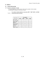
cassette is set is transmitted to the LINK SW SIZE 1/2/3 via the GEAR SECTOR
and RACK SIZE by the GUIDE ASSY END150. The three LINK SW SIZE units
turns ON or OFF respectively according to the transmitted paper size. The paper
size is detected by transmitting the ON/OFF information to the Size Switch in the
GUIDE TRAY LEFT. The types of paper that can be automatically detected are as
follows:
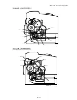
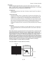
LEVER BTM LOCK and STOPPER GEAR
These are at the rear end of the cassette (i.e. the exit path of the paper). When the
cassette is inserted into the printer, the protrusions on the Feeder trigger the
mechanism that depresses the LEVER BTM LOCK, slides the RACK BTM LOCK
150, and then simultaneously unlocks the GEAR PINION and GEAR PB R of the
STOPPER GEAR.
PLATE ASSY BTM
The force pushing up the PLATE ASSY BTM is supplied via the SPRING BTM
UP150 by unlocking the LEVER BTM LOCK and STOPPER GEAR. When the
PLATE ASSY BTM is pushed up, the supplied paper and ROLL ASSY NUDGER
touch each other.
LOW INDICATOR
The LOW INDICATOR is installed only on the 550 Paper Cassette. The amount of
paper remaining in the cassette is indicated by the LOW IND FRONT. As the
amount of paper reduces, the PLATE ASSY BTM rises and the LOW IND FRONT
goes down in the GUIDE INDICATOR.
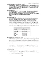
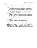
Type
Size (mm × mm)
Letter SEF
215.9 × 279.4
Legal 14" SEF
215.9 × 355.6
Legal 13" SEF
215.9 × 330.2
Executive SEF
184.2 × 266.7
A4 SEF
210.0 × 297.0
B5 (JIS) SEF
182.0 × 257.0
A5 SEF
148.5 × 210.0
Summary of Contents for 9045N
Page 1: ...Laser Printer TallyGenicom 9045N Service Manual J20006AA ...
Page 16: ...xv Blank Page ...
Page 20: ...Chapter 1 Troubleshooting Chapter 1 Troubleshooting CONTENTS Blank Page ...
Page 88: ...1 68 Chapter 1 Troubleshooting Blank Page ...
Page 160: ...1 140 Chapter 1 Troubleshooting Blank Page ...
Page 162: ...1 142 Chapter 1 Troubleshooting Blank Page ...
Page 164: ...Chapter 2 Printer Diagnostics Chapter 2 Diagnostics CONTENTS 11 Print Summary 2 16 ...
Page 194: ...1 10 Chapter 3 Removal and Replacement Procedures RRPs RRP2 150 PAPER CASSETTE ...
Page 213: ...1 29 Chapter 3 Removal and Replacement Procedures RRPs RRP3 550 PAPER CASSETTE ...
Page 240: ...1 56 Chapter 3 Removal and Replacement Procedures RRPs RRP4 150 paper Feeder ...
Page 257: ...1 73 Chapter 3 Removal and Replacement Procedures RRPs RRP5 550 Paper Feeder ...
Page 277: ...1 93 Chapter 3 Removal and Replacement Procedures RRPs RRP6 Xerographics ...
Page 302: ...1 118 Chapter 3 Removal and Replacement Procedures RRPs RRP7 500 Paper Exit ...
Page 322: ...1 138 Chapter 3 Removal and Replacement Procedures RRPs RRP8 Frame Drive ...
Page 331: ...1 147 Chapter 3 Removal and Replacement Procedures RRPs RRP9 Electrical ...
Page 394: ...1 210 Chapter 3 Removal and Replacement Procedures RRPs ...
Page 454: ...1 270 Chapter 3 Removal and Replacement Procedures RRPs Blank Page ...
Page 459: ...4 3 Chapter 4 Plug Jack P J Connector Locations Blank Page ...
Page 465: ...4 9 Chapter 4 Plug Jack P J Connector Locations 3 2 OCT Option P J Diagram ...
Page 468: ...4 12 Chapter 4 Plug Jack P J Connector Locations Blank Page ...
Page 470: ...Chapter 5 Parts Lists Chapter 5 Parts Lists CONTENTS Blank Page ...
Page 479: ...5 9 Chapter 5 Parts List Blank Page ...
Page 483: ...5 13 Chapter 5 Parts List Blank Page ...
Page 490: ...5 20 Chapter 5 Parts List PL 7 2 500 PAPER EXIT 2 2 OPTION FACE UP TRAY ILLUSTRA TION ...
Page 496: ...5 26 Chapter 5 Parts List OPTIONS PL 10 1 OPTION DUPLEX ILLUSTRATION ...
Page 501: ...5 31 Chapter 5 Parts List Blank Page ...
Page 529: ...6 19 Chapter 6 Principles of Operation J26119AA EP CARTRIDGE BTR ASSY ...
Page 531: ...6 21 Chapter 6 Principles of Operation LD Assembly JG6121AA SOS PWB Scanner Assembly ...
Page 535: ...6 25 Chapter 6 Principles of Operation ...
Page 558: ...6 48 Chapter 6 Principles of Operation Blank Page ...
Page 584: ...7 24 Chapter 7 Wiring Diagrams and Signal Information Blank Page ...
Page 608: ...Chapter 9 ESS Options Chapter 9 Controller ESS Options Contents Blank Page ...


