


1 - 95
Chapter 3 Removal and Replacement Procedures (RRPs)
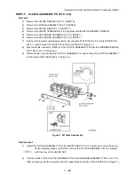
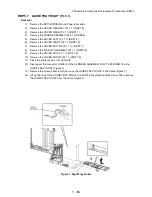
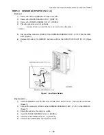
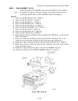
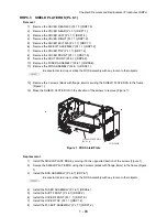
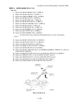
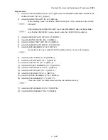
The printed circuit board on the ROS ASSEMBLY is fragile, therefore, be sure to hold it
when disconnecting the connectors (Figure 1).
16) Remove the 4 screws (black with flange, 8mm) securing the ROS ASSEMBLY to the frame.
Be careful not to drop or strike the ROS Assembly with any tools or other objects.
17) Remove the ROS ASSEMBLY.
Replacement
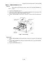
1)
Install the ROS ASSEMBLY to the frame using the 4 screws (black with flange, 8mm).
Be careful not to drop or strike the ROS Assembly with any tools or other objects.
2)
Connect the connectors of the HARNESS ASSEMBLY ROS to the printed circuit board on the
ROS ASSEMBLY.
The printed circuit board on the ROS ASSEMBLY is fragile, then, be sure to hold it with
hand when connecting the connectors.
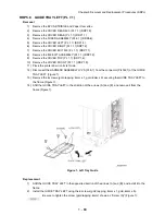
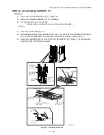
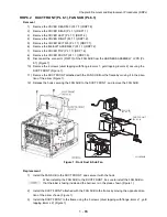
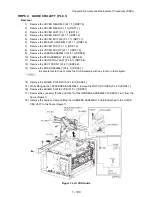
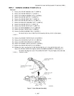
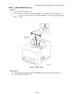
3)
Secure the harness with the 2 cable clamps on the ROS ASSEMBLY.
4)
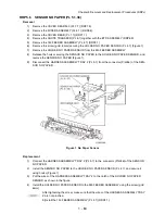
Install the PLATE TIE FRONT (PL 9.1) to the frame using the 8 screws (silver, 6mm) and tighten
firmly.
Be sure to perform this operation on a level and smooth work space.
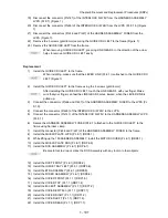
5)
Secure the harness to the PLATE TIE FRONT using the 2 clamps.
6)
Secure the DUCT VACUUM L/R (PL 6.1/PL 8.1.31) using the screw (silver with flange, 8mm).
7)
Secure the DUCT HIGH (PL 9.1) using the 3 screws (silver with flange, 8mm).
8)
Install the DUCT FRONT (PL 6.1) (RRP6.2).
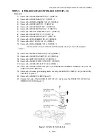
9)
Install the COVER FRONT (PL 1.1) (RRP1.5).
10) Install the COVER TOP (PL 1.1) (RRP1.4).
11) Install the 500 EXIT ASSEMBLY (PL 7.1) (RRP7.2).
12) Install the COVER EXIT 500 (PL 1.1) (RRP7.1).
13) Install the COVER RIGHT (PL 1.1) (RRP1.2).
14) Install the COVER LEFT (PL 1.1) (RRP1.3).
15) Install the COVER REAR (PL 1.1) (RRP1.1).
There are 2 kinds of screws, make sure they are installed correctly.
16) Install the COVER REAR 500 (PL 7.1) (RRP7.9).
Summary of Contents for 9045N
Page 1: ...Laser Printer TallyGenicom 9045N Service Manual J20006AA ...
Page 16: ...xv Blank Page ...
Page 20: ...Chapter 1 Troubleshooting Chapter 1 Troubleshooting CONTENTS Blank Page ...
Page 88: ...1 68 Chapter 1 Troubleshooting Blank Page ...
Page 160: ...1 140 Chapter 1 Troubleshooting Blank Page ...
Page 162: ...1 142 Chapter 1 Troubleshooting Blank Page ...
Page 164: ...Chapter 2 Printer Diagnostics Chapter 2 Diagnostics CONTENTS 11 Print Summary 2 16 ...
Page 194: ...1 10 Chapter 3 Removal and Replacement Procedures RRPs RRP2 150 PAPER CASSETTE ...
Page 213: ...1 29 Chapter 3 Removal and Replacement Procedures RRPs RRP3 550 PAPER CASSETTE ...
Page 240: ...1 56 Chapter 3 Removal and Replacement Procedures RRPs RRP4 150 paper Feeder ...
Page 257: ...1 73 Chapter 3 Removal and Replacement Procedures RRPs RRP5 550 Paper Feeder ...
Page 277: ...1 93 Chapter 3 Removal and Replacement Procedures RRPs RRP6 Xerographics ...
Page 302: ...1 118 Chapter 3 Removal and Replacement Procedures RRPs RRP7 500 Paper Exit ...
Page 322: ...1 138 Chapter 3 Removal and Replacement Procedures RRPs RRP8 Frame Drive ...
Page 331: ...1 147 Chapter 3 Removal and Replacement Procedures RRPs RRP9 Electrical ...
Page 394: ...1 210 Chapter 3 Removal and Replacement Procedures RRPs ...
Page 454: ...1 270 Chapter 3 Removal and Replacement Procedures RRPs Blank Page ...
Page 459: ...4 3 Chapter 4 Plug Jack P J Connector Locations Blank Page ...
Page 465: ...4 9 Chapter 4 Plug Jack P J Connector Locations 3 2 OCT Option P J Diagram ...
Page 468: ...4 12 Chapter 4 Plug Jack P J Connector Locations Blank Page ...
Page 470: ...Chapter 5 Parts Lists Chapter 5 Parts Lists CONTENTS Blank Page ...
Page 479: ...5 9 Chapter 5 Parts List Blank Page ...
Page 483: ...5 13 Chapter 5 Parts List Blank Page ...
Page 490: ...5 20 Chapter 5 Parts List PL 7 2 500 PAPER EXIT 2 2 OPTION FACE UP TRAY ILLUSTRA TION ...
Page 496: ...5 26 Chapter 5 Parts List OPTIONS PL 10 1 OPTION DUPLEX ILLUSTRATION ...
Page 501: ...5 31 Chapter 5 Parts List Blank Page ...
Page 529: ...6 19 Chapter 6 Principles of Operation J26119AA EP CARTRIDGE BTR ASSY ...
Page 531: ...6 21 Chapter 6 Principles of Operation LD Assembly JG6121AA SOS PWB Scanner Assembly ...
Page 535: ...6 25 Chapter 6 Principles of Operation ...
Page 558: ...6 48 Chapter 6 Principles of Operation Blank Page ...
Page 584: ...7 24 Chapter 7 Wiring Diagrams and Signal Information Blank Page ...
Page 608: ...Chapter 9 ESS Options Chapter 9 Controller ESS Options Contents Blank Page ...


