


1 – 128
Chapter 1 Troubleshooting
6
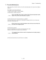
Checking Heat Roll and Pressure Roll
Remove FUSER ASSY. (RRP8.8)
Warning; Start the operation after the FUSER ASSY
have cooled down.
Turn the Gear HR with a finger, and check the Heat Roll
and Pressure Roll.
Are the Heat Roll and Pressure Roll damaged or
stained?
Go to step 7.
Replace FUSER
ASSY. (RRP8.8)
7
Checking ground of Heat Roll, Pressure Roll and Inlet
Chute Check visually, if there are any stains or transfor-
mation on the two plates on the left side of FUSER
ASSY.
Check the continuity between the plate on the left side
of FUSER ASSY and the following points:
- Back plate and Both ends of Heat Roll, without coating
(5-10 k-ohm)
- Front plate and The plate on Inlet Chute left end (1-2
k-ohm)
Are the grounding plates of Heat Roll, Pressure Roll
and Inlet Chute sound and continuous?
Go to step 8.
Replace FUSER
ASSY. (RRP8.8)
8
Checking ground of FUSER ASSY
Remove EP CARTRIDGE.
Check if there are any stains or deformation on GEAR
ASSY HOUSING.
Check the continuity between the printer frame and
screw on the back of FUSER ASSY.
Are there any deformation or stains on GEAR ASSY
HOUSING? Is FUSER ASSY grounded?
Go to step [ESS
and possible
causes].
Replace GEAR
ASSY HOUSING.
(RRP11.3)
Step Check
Yes
No
Summary of Contents for 9045N
Page 1: ...Laser Printer TallyGenicom 9045N Service Manual J20006AA ...
Page 16: ...xv Blank Page ...
Page 20: ...Chapter 1 Troubleshooting Chapter 1 Troubleshooting CONTENTS Blank Page ...
Page 88: ...1 68 Chapter 1 Troubleshooting Blank Page ...
Page 160: ...1 140 Chapter 1 Troubleshooting Blank Page ...
Page 162: ...1 142 Chapter 1 Troubleshooting Blank Page ...
Page 164: ...Chapter 2 Printer Diagnostics Chapter 2 Diagnostics CONTENTS 11 Print Summary 2 16 ...
Page 194: ...1 10 Chapter 3 Removal and Replacement Procedures RRPs RRP2 150 PAPER CASSETTE ...
Page 213: ...1 29 Chapter 3 Removal and Replacement Procedures RRPs RRP3 550 PAPER CASSETTE ...
Page 240: ...1 56 Chapter 3 Removal and Replacement Procedures RRPs RRP4 150 paper Feeder ...
Page 257: ...1 73 Chapter 3 Removal and Replacement Procedures RRPs RRP5 550 Paper Feeder ...
Page 277: ...1 93 Chapter 3 Removal and Replacement Procedures RRPs RRP6 Xerographics ...
Page 302: ...1 118 Chapter 3 Removal and Replacement Procedures RRPs RRP7 500 Paper Exit ...
Page 322: ...1 138 Chapter 3 Removal and Replacement Procedures RRPs RRP8 Frame Drive ...
Page 331: ...1 147 Chapter 3 Removal and Replacement Procedures RRPs RRP9 Electrical ...
Page 394: ...1 210 Chapter 3 Removal and Replacement Procedures RRPs ...
Page 454: ...1 270 Chapter 3 Removal and Replacement Procedures RRPs Blank Page ...
Page 459: ...4 3 Chapter 4 Plug Jack P J Connector Locations Blank Page ...
Page 465: ...4 9 Chapter 4 Plug Jack P J Connector Locations 3 2 OCT Option P J Diagram ...
Page 468: ...4 12 Chapter 4 Plug Jack P J Connector Locations Blank Page ...
Page 470: ...Chapter 5 Parts Lists Chapter 5 Parts Lists CONTENTS Blank Page ...
Page 479: ...5 9 Chapter 5 Parts List Blank Page ...
Page 483: ...5 13 Chapter 5 Parts List Blank Page ...
Page 490: ...5 20 Chapter 5 Parts List PL 7 2 500 PAPER EXIT 2 2 OPTION FACE UP TRAY ILLUSTRA TION ...
Page 496: ...5 26 Chapter 5 Parts List OPTIONS PL 10 1 OPTION DUPLEX ILLUSTRATION ...
Page 501: ...5 31 Chapter 5 Parts List Blank Page ...
Page 529: ...6 19 Chapter 6 Principles of Operation J26119AA EP CARTRIDGE BTR ASSY ...
Page 531: ...6 21 Chapter 6 Principles of Operation LD Assembly JG6121AA SOS PWB Scanner Assembly ...
Page 535: ...6 25 Chapter 6 Principles of Operation ...
Page 558: ...6 48 Chapter 6 Principles of Operation Blank Page ...
Page 584: ...7 24 Chapter 7 Wiring Diagrams and Signal Information Blank Page ...
Page 608: ...Chapter 9 ESS Options Chapter 9 Controller ESS Options Contents Blank Page ...


