


6 – 46
Chapter 6 Principles of Operation
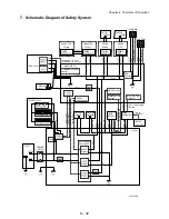
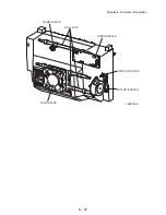
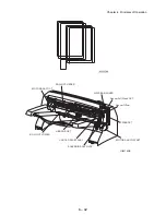
16. Actions of Main Functional Components
The Option 550 Feeder is available as an optional feeder for JIGEN laser printer. The
Paper Cassette installed in the optical feeder is identical in function with the standard
Paper Cassette used by the base engine, and so the description of the Paper Cassette
is omitted here.
OPT ASSY SIZE
A switch for setting the size of paper supplied from Paper Cassette is mounted. A
signal indicating the set size is transmitted as a voltage to the MCU side of HVPS/
MCU.
ACTUATOR NO PAPER
If paper runs out in the Paper Cassette, the ACTUATOR NO PAPER drops and the
flag of the ACTUATOR NO PAPER that shielded the detection portion of the
SENSOR NO PAPEER moves off the detection portion. Thus, the light is
transmitted.
SENSOR NO PAPER
The presence or absence of paper in the Paper Cassette is detected by the position
of the ACTUATOR NO PAPER. This is converted into an electrical signal. If the
detection portion is shielded (i.e., there is paper), /NO PAPER FEED 550 SNR ON
signal is turned OFF.
ACTUATOR LOW PAPER
When paper is low in the Paper Cassette, the arm of the ACTUATOR LOW PAPER
is pushed up by the PLATE ASSY BTM. The flag of the ACTUATOR LOW PAPER
that shielded the detection portion of the SENSOR LOW PAPER moves off the
detection portion. Thus, the light is transmitted.
SENSOR LOW PAPER
The state that paper is low in the Paper Cassette is detected by the position of the
ACTUATOR LOW PAPER. This is converted into an electrical signal. If the
detection portion is shielded (i.e., paper is high), /LOW PAPER FEED 550 SNR ON
signal is turned OFF.
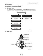
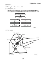
550 FEEDER OPTION
This is a mechanism for supplying paper from the Paper Cassette into the printer.
The driving force from the MOTOR FEEDER is transmitted via the CLUTCH ASSY
PH to the ROLL ASSY FEED and ROLL ASSY NUDGER. Thus, the paper is
transported. When the ROLL ASSY NUDGER picks up some sheets of paper and
the paper gets low, the position of the ROLL ASSY NUDGER drops accordingly.
The lowered ROLL ASSY NUDGER pushes down the lock lever of the PLATE
ASSY BTM, releasing it. The PLATE ASSY BTM is pushed up by a spring, and thus
the paper is raised. The raised paper then raises the SUPPORT NUDGER. The
SUPPORT NUDGER disengages from the lock lever of the PLATE ASSY BTM.
The PLATE ASSY BTM stops moving upward.
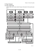
ROLL ASSY TURN
This roll conveys the paper into the printer after the paper is transported by the
ROLL ASSY FEED and ROLL ASSY NUDGER. The driving power from the
Summary of Contents for 9045N
Page 1: ...Laser Printer TallyGenicom 9045N Service Manual J20006AA ...
Page 16: ...xv Blank Page ...
Page 20: ...Chapter 1 Troubleshooting Chapter 1 Troubleshooting CONTENTS Blank Page ...
Page 88: ...1 68 Chapter 1 Troubleshooting Blank Page ...
Page 160: ...1 140 Chapter 1 Troubleshooting Blank Page ...
Page 162: ...1 142 Chapter 1 Troubleshooting Blank Page ...
Page 164: ...Chapter 2 Printer Diagnostics Chapter 2 Diagnostics CONTENTS 11 Print Summary 2 16 ...
Page 194: ...1 10 Chapter 3 Removal and Replacement Procedures RRPs RRP2 150 PAPER CASSETTE ...
Page 213: ...1 29 Chapter 3 Removal and Replacement Procedures RRPs RRP3 550 PAPER CASSETTE ...
Page 240: ...1 56 Chapter 3 Removal and Replacement Procedures RRPs RRP4 150 paper Feeder ...
Page 257: ...1 73 Chapter 3 Removal and Replacement Procedures RRPs RRP5 550 Paper Feeder ...
Page 277: ...1 93 Chapter 3 Removal and Replacement Procedures RRPs RRP6 Xerographics ...
Page 302: ...1 118 Chapter 3 Removal and Replacement Procedures RRPs RRP7 500 Paper Exit ...
Page 322: ...1 138 Chapter 3 Removal and Replacement Procedures RRPs RRP8 Frame Drive ...
Page 331: ...1 147 Chapter 3 Removal and Replacement Procedures RRPs RRP9 Electrical ...
Page 394: ...1 210 Chapter 3 Removal and Replacement Procedures RRPs ...
Page 454: ...1 270 Chapter 3 Removal and Replacement Procedures RRPs Blank Page ...
Page 459: ...4 3 Chapter 4 Plug Jack P J Connector Locations Blank Page ...
Page 465: ...4 9 Chapter 4 Plug Jack P J Connector Locations 3 2 OCT Option P J Diagram ...
Page 468: ...4 12 Chapter 4 Plug Jack P J Connector Locations Blank Page ...
Page 470: ...Chapter 5 Parts Lists Chapter 5 Parts Lists CONTENTS Blank Page ...
Page 479: ...5 9 Chapter 5 Parts List Blank Page ...
Page 483: ...5 13 Chapter 5 Parts List Blank Page ...
Page 490: ...5 20 Chapter 5 Parts List PL 7 2 500 PAPER EXIT 2 2 OPTION FACE UP TRAY ILLUSTRA TION ...
Page 496: ...5 26 Chapter 5 Parts List OPTIONS PL 10 1 OPTION DUPLEX ILLUSTRATION ...
Page 501: ...5 31 Chapter 5 Parts List Blank Page ...
Page 529: ...6 19 Chapter 6 Principles of Operation J26119AA EP CARTRIDGE BTR ASSY ...
Page 531: ...6 21 Chapter 6 Principles of Operation LD Assembly JG6121AA SOS PWB Scanner Assembly ...
Page 535: ...6 25 Chapter 6 Principles of Operation ...
Page 558: ...6 48 Chapter 6 Principles of Operation Blank Page ...
Page 584: ...7 24 Chapter 7 Wiring Diagrams and Signal Information Blank Page ...
Page 608: ...Chapter 9 ESS Options Chapter 9 Controller ESS Options Contents Blank Page ...


