


Chapter 3 Removal and Replacement Procedures (RRPs)
Chapter 3 Removal and Replacement Procedures (RRPs) CONTENTS
RRP12.3 COVER LEFT PLATE (PL12.1)........................................................................................... 3 - 216
RRP12.4 OPT ASSY SIZE (PL12.1)................................................................................................... 3 - 217
RRP12.5 DRIVE ASSY OPT FDR (PL12.1) ....................................................................................... 3 - 218
RRP12.6 MOTOR FEEDER (PL12.1)................................................................................................. 3 - 220
RRP12.7 SENSOR LOW PAPER (PL12.1) ........................................................................................ 3 - 221
RRP12.8 PWBA FEEDER 550 (PL12.1) ............................................................................................ 3 - 222
RRP12.9 550 FEEDER OPTION (PL12.2) ......................................................................................... 3 - 224
RRP12.10 ROLL ASSY NUDGER (PL12.2), ROLL ASSY FEED (PL12.2)........................................ 3 - 227
RRP12.11 CLUTCH ONEWAY NUDGER (PL12.2) ........................................................................... 3 - 229
RRP12.12 GEAR NUDGER (PL12.2)................................................................................................. 3 - 230
RRP12.13 ROLL ASSY TURN (PL12.2)............................................................................................. 3 - 233
RRP12.14 CLUTCH ASSY PH (PL12.2) ............................................................................................ 3 - 234
RRP12.15 CLUTCH PR-REGI (PL12.2) ............................................................................................. 3 - 236
RRP12.16 SENSOR NO PAPER (PL12.2)......................................................................................... 3 - 237
RRP12.17 ROLL ASSY RETARD (PL12.2)........................................................................................ 3 - 238
RRP12.18 RACK SIZE (PL12.3)......................................................................................................... 3 - 241
RRP12.19 GEAR SECTOR (PL12.3) ................................................................................................. 3 - 247
RRP12.20 GUIDE ASSY END 550 (PL12.3) ...................................................................................... 3 - 250
RRP12.21 PLATE ASSY BTM (PL12.3) ............................................................................................. 3 - 253
RRP12.22 GEAR LEVER LOCK (PL12.3), LEVER BTM LOCK (PL12.3).......................................... 3 - 257
RRP12.23 HANDLE EXTENSION 550 (PL12.1) ................................................................................ 3 - 261
RRP12.24 GUIDE INDICATOR 3 (PL12.3) ........................................................................................ 3 - 262
RRP12.25 GUIDE INDICATOR 2 (PL12.3) ........................................................................................ 3 - 264
RRP12.26 LOW IND FRONT (PL12.3)............................................................................................... 3 - 267
RRP12.27 SPRING EARTH TOP (PL12.2) ........................................................................................ 3 - 269
Summary of Contents for 9045N
Page 1: ...Laser Printer TallyGenicom 9045N Service Manual J20006AA ...
Page 16: ...xv Blank Page ...
Page 20: ...Chapter 1 Troubleshooting Chapter 1 Troubleshooting CONTENTS Blank Page ...
Page 88: ...1 68 Chapter 1 Troubleshooting Blank Page ...
Page 160: ...1 140 Chapter 1 Troubleshooting Blank Page ...
Page 162: ...1 142 Chapter 1 Troubleshooting Blank Page ...
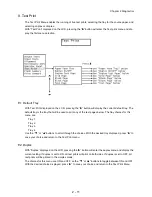
Page 164: ...Chapter 2 Printer Diagnostics Chapter 2 Diagnostics CONTENTS 11 Print Summary 2 16 ...
Page 194: ...1 10 Chapter 3 Removal and Replacement Procedures RRPs RRP2 150 PAPER CASSETTE ...
Page 213: ...1 29 Chapter 3 Removal and Replacement Procedures RRPs RRP3 550 PAPER CASSETTE ...
Page 240: ...1 56 Chapter 3 Removal and Replacement Procedures RRPs RRP4 150 paper Feeder ...
Page 257: ...1 73 Chapter 3 Removal and Replacement Procedures RRPs RRP5 550 Paper Feeder ...
Page 277: ...1 93 Chapter 3 Removal and Replacement Procedures RRPs RRP6 Xerographics ...
Page 302: ...1 118 Chapter 3 Removal and Replacement Procedures RRPs RRP7 500 Paper Exit ...
Page 322: ...1 138 Chapter 3 Removal and Replacement Procedures RRPs RRP8 Frame Drive ...
Page 331: ...1 147 Chapter 3 Removal and Replacement Procedures RRPs RRP9 Electrical ...
Page 394: ...1 210 Chapter 3 Removal and Replacement Procedures RRPs ...
Page 454: ...1 270 Chapter 3 Removal and Replacement Procedures RRPs Blank Page ...
Page 459: ...4 3 Chapter 4 Plug Jack P J Connector Locations Blank Page ...
Page 465: ...4 9 Chapter 4 Plug Jack P J Connector Locations 3 2 OCT Option P J Diagram ...
Page 468: ...4 12 Chapter 4 Plug Jack P J Connector Locations Blank Page ...
Page 470: ...Chapter 5 Parts Lists Chapter 5 Parts Lists CONTENTS Blank Page ...
Page 479: ...5 9 Chapter 5 Parts List Blank Page ...
Page 483: ...5 13 Chapter 5 Parts List Blank Page ...
Page 490: ...5 20 Chapter 5 Parts List PL 7 2 500 PAPER EXIT 2 2 OPTION FACE UP TRAY ILLUSTRA TION ...
Page 496: ...5 26 Chapter 5 Parts List OPTIONS PL 10 1 OPTION DUPLEX ILLUSTRATION ...
Page 501: ...5 31 Chapter 5 Parts List Blank Page ...
Page 529: ...6 19 Chapter 6 Principles of Operation J26119AA EP CARTRIDGE BTR ASSY ...
Page 531: ...6 21 Chapter 6 Principles of Operation LD Assembly JG6121AA SOS PWB Scanner Assembly ...
Page 535: ...6 25 Chapter 6 Principles of Operation ...
Page 558: ...6 48 Chapter 6 Principles of Operation Blank Page ...
Page 584: ...7 24 Chapter 7 Wiring Diagrams and Signal Information Blank Page ...
Page 608: ...Chapter 9 ESS Options Chapter 9 Controller ESS Options Contents Blank Page ...


