


1 - 3
Chapter 3 Removal and Replacement Procedures (RRPs)
1.4 Description of procedures
"RRP X,Y "AAAAA" at the top of procedures represent the part name AAAAA are to be removed
and replaced.
"(PL X.Y.Z)" following the parts name in procedures represent that the parts are those of the plate
(PL) "X.Y", item "Z" in Chapter 5, Parts List. Their forms, replacing position or other conditions can
be seen in Chapter 5, Parts List.
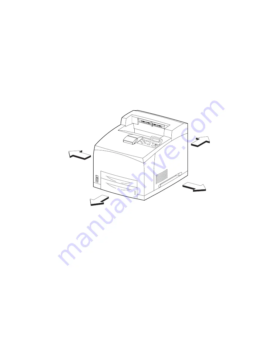
In the procedures, directions are represented as follows.
- Front: Front when you are facing the front of this laser printer.
- Rear: Inner direction when you are facing the front of this laser printer.
- Left: Left hand when you are facing the front of this laser printer.
- Right: Right hand when you are facing the front of this laser printer.
The screws in procedures are expressed with their replacing position, color, characteristics and
nominal length, etc.
“In case of _____ specifications" in the procedures indicate that service operation should be pro-
vided only to laser printer of specified specifications (service operation should not be provided for
laser printer of specifications not covered).
"RRP X.Y" in the midst or at the end of sentences in the procedures indicate that work procedures
related with the "RRP X.Y" are described.
"Figure X.Y" at the end of the sentences of procedures indicate that illustrations instructive for the
"RRP X.Y" are included.
"Z)" in the illustrations correspond to "Z)" of the service procedures.
The screws in the illustrations should be removed using a plus (+) screwdriver unless otherwise
specified.
A black arrow in the illustrations indicate movement in the arrow mark direction. Numbered black
arrows indicate movement in the order of the numbers.
White arrows (FRONT) in the illustrations indicate the front direction.
For the positions of the connectors (P/J), refer to Chapter 7, Electric wiring.
JG3205AA
LEFT
FRONT
RIGHT
REAR
Summary of Contents for 9045N
Page 1: ...Laser Printer TallyGenicom 9045N Service Manual J20006AA ...
Page 16: ...xv Blank Page ...
Page 20: ...Chapter 1 Troubleshooting Chapter 1 Troubleshooting CONTENTS Blank Page ...
Page 88: ...1 68 Chapter 1 Troubleshooting Blank Page ...
Page 160: ...1 140 Chapter 1 Troubleshooting Blank Page ...
Page 162: ...1 142 Chapter 1 Troubleshooting Blank Page ...
Page 164: ...Chapter 2 Printer Diagnostics Chapter 2 Diagnostics CONTENTS 11 Print Summary 2 16 ...
Page 194: ...1 10 Chapter 3 Removal and Replacement Procedures RRPs RRP2 150 PAPER CASSETTE ...
Page 213: ...1 29 Chapter 3 Removal and Replacement Procedures RRPs RRP3 550 PAPER CASSETTE ...
Page 240: ...1 56 Chapter 3 Removal and Replacement Procedures RRPs RRP4 150 paper Feeder ...
Page 257: ...1 73 Chapter 3 Removal and Replacement Procedures RRPs RRP5 550 Paper Feeder ...
Page 277: ...1 93 Chapter 3 Removal and Replacement Procedures RRPs RRP6 Xerographics ...
Page 302: ...1 118 Chapter 3 Removal and Replacement Procedures RRPs RRP7 500 Paper Exit ...
Page 322: ...1 138 Chapter 3 Removal and Replacement Procedures RRPs RRP8 Frame Drive ...
Page 331: ...1 147 Chapter 3 Removal and Replacement Procedures RRPs RRP9 Electrical ...
Page 394: ...1 210 Chapter 3 Removal and Replacement Procedures RRPs ...
Page 454: ...1 270 Chapter 3 Removal and Replacement Procedures RRPs Blank Page ...
Page 459: ...4 3 Chapter 4 Plug Jack P J Connector Locations Blank Page ...
Page 465: ...4 9 Chapter 4 Plug Jack P J Connector Locations 3 2 OCT Option P J Diagram ...
Page 468: ...4 12 Chapter 4 Plug Jack P J Connector Locations Blank Page ...
Page 470: ...Chapter 5 Parts Lists Chapter 5 Parts Lists CONTENTS Blank Page ...
Page 479: ...5 9 Chapter 5 Parts List Blank Page ...
Page 483: ...5 13 Chapter 5 Parts List Blank Page ...
Page 490: ...5 20 Chapter 5 Parts List PL 7 2 500 PAPER EXIT 2 2 OPTION FACE UP TRAY ILLUSTRA TION ...
Page 496: ...5 26 Chapter 5 Parts List OPTIONS PL 10 1 OPTION DUPLEX ILLUSTRATION ...
Page 501: ...5 31 Chapter 5 Parts List Blank Page ...
Page 529: ...6 19 Chapter 6 Principles of Operation J26119AA EP CARTRIDGE BTR ASSY ...
Page 531: ...6 21 Chapter 6 Principles of Operation LD Assembly JG6121AA SOS PWB Scanner Assembly ...
Page 535: ...6 25 Chapter 6 Principles of Operation ...
Page 558: ...6 48 Chapter 6 Principles of Operation Blank Page ...
Page 584: ...7 24 Chapter 7 Wiring Diagrams and Signal Information Blank Page ...
Page 608: ...Chapter 9 ESS Options Chapter 9 Controller ESS Options Contents Blank Page ...


